Two quaternion records can differ in all four signs and still describe exactly the same orientation. That becomes a practical problem when you blend the records as vectors: q and −q cancel at an uncorrected midpoint. With different endpoint orientations, choosing the opposite sign can instead send the intermediate tool poses along a different rotation path.
For a custom normalized linear interpolation (NLERP), establish unit inputs, component order and a path convention before blending. Compare intermediate poses as well as endpoints. These examples use our explicit formula; they do not test a Blender interpolation API or robot controller.
A stationary orientation can produce an undefined midpoint
Take a unit quaternion q for a 20° rotation about Z. Use −q as the other endpoint. Both endpoints rotate every vector in exactly the same way. However, the component-wise midpoint is (q + (−q))/2 = 0. Dividing that zero vector by its length cannot produce a unit quaternion.
The correct record for this particular failed calculation is undefined. Substituting the previous pose or identity would hide the failure and introduce a separate policy. Away from the midpoint, normalizing this same-pose blend returns q or −q, so the geometry stays in the same orientation. A change in the quaternion sign does not itself mean the object has made a full turn.
The sign equivalence is visible in Blender’s inspected quaternion-to-matrix source: its rotation entries use products of quaternion components. Negating every component preserves those products. This is a reading of the pinned source and the underlying rotation formula; no quaternion API was executed for this example.
The endpoint remains 100°, but the midpoint becomes −120°
Now start at Z=20° and finish at Z=100°. Store the target using the negative of its usual unit-quaternion representative. Normalize a linear blend without adjusting that sign and the halfway orientation is −120°. Adjust the target sign before blending and the halfway orientation is +60°.
Both paths still end at the same physical 100° orientation. The difference is in the intermediate poses. For this Z-axis example, the unadjusted branch travels from 20° toward −260°, which is the same endpoint orientation as +100°. The adjusted branch goes from 20° toward +100°.
To make the geometric consequence visible, the native study uses an asymmetric two-box tool with a tip landmark at (120,35,20) mm in tool coordinates. Its distance from the rotation axis is 125 mm. The two midpoint orientations differ by 180°, putting that landmark 250 mm apart when the tool origins coincide. Those are synthetic rigid-geometry calculations, not a measured robot error or collision clearance.
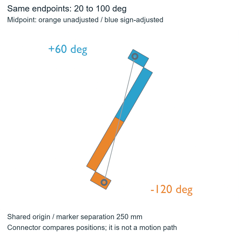
For this shorter-path convention, compare the unit endpoint quaternions with a dot product. If it is negative, negate all four components of one endpoint before blending. The inspected Blender interpolation helper also checks the dot-product sign before its spherical interpolation weights. Our example instead uses normalized linear interpolation, commonly called NLERP; it does not reproduce that helper’s weighting or claim constant angular speed.
The code uses scalar-first (w,x,y,z) order, also documented for Blender quaternions. Component order must be explicit when copying an example into another system.
from math import radians, cos, sin, sqrt, atan2, degrees

# Scalar-first (w,x,y,z), unit inputs. This is our NLERP, not a library API.
def qz(angle):
    a = radians(angle)/2
    return (cos(a), 0, 0, sin(a))

def nlerp(a, b, t, adjust):
    if adjust and sum(x*y for x, y in zip(a, b)) < 0:
        b = tuple(-x for x in b)
    blend = tuple((1-t)*x+t*y for x, y in zip(a, b))
    length = sqrt(sum(x*x for x in blend))
    if length == 0:
        return None  # no rotation exists for the zero quaternion
    return tuple(x/length for x in blend)

a = qz(20)
for label, target in [('same pose', a), ('20 to 100 degrees', qz(100))]:
    negative_target = tuple(-x for x in target)
    for adjust in (False, True):
        samples = []
        for t in (0, .25, .5, .75, 1):
            q = nlerp(a, negative_target, t, adjust)
            # This signed angle tracks this chosen Z-axis example, not all rotations.
            samples.append(None if q is None else round(degrees(2*atan2(q[3], q[0])), 3))
        print(label, 'sign adjustment:', adjust, samples)
assert nlerp(a, tuple(-x for x in a), .5, False) is None
assert max(abs(x-y) for x, y in zip(nlerp(a, tuple(-x for x in a), .5, True), a)) < 1e-12
The printed angles retain the chosen quaternion representative: −340° and +20° describe the same stationary orientation, just as −260° and +100° describe the same final orientation. None is the actual undefined midpoint of the unadjusted same-pose formula. No motion is inferred from a printed angle’s extra turn.
The AI-operated Blender 5.2.2 LTS study on October 5, 2026 created five prescribed samples for each of four branches: twenty records, nineteen valid finite poses and thirty-eight meshes. The exact undefined midpoint has no quaternion, matrix, object or invented measurement. Each tool consists of two finite boxes with sixteen labeled vertices, twenty-four edges and twelve faces, accompanied by origin, 30 mm XYZ and tip landmarks.
An independent calculation used complex half-angle arithmetic and Rodrigues vector rotations to audit every evaluated world matrix, finite vertex, topology, rigid distance and landmark direction. The actual raw and sign-adjusted midpoints returned approximately −120° and +60° after removing a common proper XYZ rotation of (15,−20,25)°. Removing their known display translations put the corresponding tip markers approximately 250 mm apart. The two physical endpoint poses agreed across both branches.
Geometry comparisons used 4 micrometers, triad consistency used 0.00003 and angle consistency used 0.002°. These are numerical guards, not robot accuracy. The native scene received our prescribed matrices; no quaternion interpolation API, keyframe animation, collision check, robot controller or hardware was run. The pinned source is a separately inspected implementation, not a verified source revision for the installed Blender build. The parameter t is a blend fraction, not elapsed physical time; neither these samples nor a shorter orientation path establish controller feasibility or collision safety.
Sign adjustment also cannot recover an intended long spin from endpoint orientations alone. A 180° relative rotation has an equal-path tie, and nearly cancelling inputs need a numerical policy beyond this exact-zero demonstration. For a custom blend, establish unit inputs, component order and the desired path convention, then inspect intermediate poses as well as endpoint agreement.
The mirrored-mesh pose study addresses a different boundary: reflected shape cannot be reproduced by a proper quaternion pose. Here every valid pose is a proper rotation; the implementation decision is which intermediate path a pair of endpoint representatives produces.