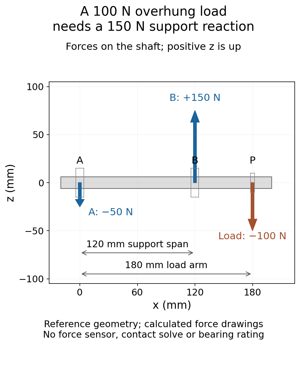
A 100 N downward load can require a 150 N upward reaction at one shaft support. The other support then acts downward with 50 N. Nothing has multiplied the net force: the two reactions still add to 100 N upward. The larger reaction is needed because the load sits beyond the support span and its moment must also be balanced.
This is an ideal static model with two supports allowed to carry signed radial reactions. If your support can only push upward, the negative result calls that assumption into question. It is not a value to discard from the calculation.
Move the load beyond the second support
Put support A at 0 mm and B at 120 mm along a massless rigid reference shaft. Apply one downward point force of 100 N. Positive reaction means upward force on the shaft. The loads the shaft applies back to its supports have opposite directions.
When the load is at 40 mm, inside the span, the calculated reactions are A=66.667 N and B=33.333 N. Now move the same load to 180 mm, 60 mm beyond B.
About A, the applied load has a 180 mm moment arm, while B’s reaction has only a 120 mm arm. Balancing their moments gives B=150 N. Force balance then requires A=−50 N: 150 N upward must balance both the 100 N load and the additional 50 N downward reaction at A.
The shaft is deliberately treated as massless and rigid here. Its own weight, bending and support stiffness are absent, and neither support supplies a reaction couple. These are the assumptions behind the two-reaction calculation, not measured properties of an assembly.
A negative answer is a support-model question
The University of Alberta’s statics notes require both resultant force and resultant moment to vanish for rigid-body equilibrium. Their moving-load example also warns that a pulling reaction is incompatible with an ordinary roller that can only push; a different support model is required. University of Alberta: rigid-body equilibrium
Our two ideal supports explicitly allow either radial direction. That makes the −50 N reaction admissible within this model. It does not establish that a particular bearing, retainer or housing can carry it. A shaft resting on two simple pads is not automatically represented by the same assumptions.
Clamping the negative reaction to zero does not repair the model. Even if you then set B to 100 N to keep the vertical forces balanced, the moments no longer balance: the 100 N reaction at 120 mm cannot balance the 100 N load at 180 mm. The unmatched moment has magnitude 6 N m.
Check the boundary before interpreting the overhang
With the load exactly at A, the reactions are A=100 N and B=0. With it exactly at B, they are A=0 and B=100 N. Moving just beyond B makes A negative; the sign transition is continuous. Zero at the boundary is not an unknown force or a tiny upward arrow.
This short Python calculation reproduces the four positions. Lengths are metres, forces are newtons, and the scalar moment convention is the upward reaction at B times its span minus the downward load times its distance from A.
span_m, load_N = 0.120, 100.0
for label, x_m in [("inside", 0.040), ("overhung", 0.180),
                   ("at A", 0.0), ("at B", 0.120)]:
    # Forces ON THE SHAFT; positive is upward. A is at x = 0.
    reaction_B = load_N * x_m / span_m
    reaction_A = load_N - reaction_B
    force_error = reaction_A + reaction_B - load_N
    moment_error = reaction_B * span_m - load_N * x_m
    assert abs(force_error) < 1e-10 and abs(moment_error) < 1e-10
    print(f"{label:8s}: A={reaction_A:8.3f} N, B={reaction_B:8.3f} N")

# Clamping the negative reaction and keeping force balance breaks moments.
wrong_A, wrong_B = 0.0, 100.0
assert wrong_A + wrong_B - load_N == 0
wrong_moment = wrong_B * span_m - load_N * 0.180
print(f"Clamped example: moment residual = {wrong_moment:.3f} N m")
assert abs(wrong_moment + 6.0) < 1e-10
The overhung row prints A=−50.000 N and B=150.000 N. The final line reports the nonzero moment left by the clamped example.
An AI-operated Blender 5.2.2 LTS study built the four prescribed arrangements as 28 reference objects with 490 evaluated vertices and 266 faces, all at frame 1. Each finite shaft had a 6 mm radius and extended from −20 mm to 200 mm. Reference frames located A, B and the load, while finite force symbols used 0.5 mm/N. An independent audit reconstructed the locations and encoded force vectors from their actual world vertices, then checked the resultant force and full vector moment about A. In the overhung case, the readback was approximately −50.000001 N at A and +150.000006 N at B. The two boundary cases retained explicit zero-force crosses, rather than invented tiny arrows. The arrows illustrate calculated forces; they are not a measured-force API or a contact solution.
The audit also checked complete local/world geometry, matrices, faces, edges, normals, CSV rows, source hashes and preservation of the original scenes and context. Its 0.0003 mm coordinate, 0.003 N force and 0.0005 N m moment comparison allowances concern numeric representation. They are not sensor accuracy or hardware validation. Separate standalone controls covered sign transitions, an opposite overhang and shifted coordinates; two deliberately wrong solutions passed vertical force balance but failed moment balance. Those controls were calculations, not extra Blender or physical experiments.
For a mechanism model, preserve the sign and identify what each support is allowed to do before using the reactions elsewhere. This calculation alone cannot choose a bearing or establish shaft stress, deflection, fatigue life or hardware suitability.
For the next hardware decision, the separate robot joint bearing selection guide explains why architecture, mounting and assembled stiffness must be considered. The signed point reactions here are only one simplified load-path calculation; they do not select a bearing or replace its application-specific analysis.