When MoveIt Task Constructor produces plausible results inside individual stages but never assembles a complete serial task, do not begin by tuning the motion planner. First trace which stage writes each interface, which neighbor reads it, which successful solution feeds a monitoring generator, and whether the two scene hypotheses are compatible enough to be paired.
This separates four failures that can look alike from the outside: incompatible stage directions, an absent monitored solution, incompatible interface states, and a property that was never explicitly exposed or initialized from the intended source. A connector can have valid planners and still receive no usable pair of start and end states.
The source claims below are pinned to the MoveIt Task Constructor ROS 2 branch at commit f527048b3db1574f68f5c646e9ed7099085af5c8, dated September 10, 2026. This is an examined upstream commit, not a released package, installed version or compatibility promise. No MoveIt, MTC, ROS, planner or robot code was run for this article.
Start with the stage ports
The pinned Stage interface flags describe what a stage reads and writes. A generator writes states toward both neighbors without consuming an adjacent input. A forward propagator reads a start state and writes the next start state. A backward propagator reads an end state and writes the previous end state. A connector reads a start from one side and an end from the other.
The serial container does not treat every neighboring pair as interchangeable. Its adjacency wiring connects a stage that writes a next-start interface to a neighbor that reads a start, or a stage that reads an end to a neighbor that writes a previous-end interface. An incompatible sequence becomes an initialization error rather than a difficult planning problem.
For each boundary, write down four facts:
| Boundary question | Evidence to capture |
|---|---|
| Who produces the state? | Stage name, type and write direction |
| Who consumes it? | Neighbor stage and read direction |
| What crosses the boundary? | Interface state, linked solution and forwarded properties |
| What happens next? | Propagation, monitoring callback, connector pairing or initialization refusal |
A list of stage names is not enough. A sequence such as generator → forward propagator → connector → backward propagator → generator has compatible directional roles. Reversing one propagator or placing two producers together can break the handoff before any planner is asked to solve a motion.
A monitoring generator needs a successful source solution
A monitoring generator does not merely look up a stage by name when it wants data. In the examined MonitoringGenerator implementation, initialization requires a monitored stage. The generator registers a solution callback, and only successful solutions are forwarded to its onNewSolution() path.
This creates a useful diagnostic boundary. If the monitored stage has no successful solution, the generator has no successful event to consume. If the wrong stage is monitored, a nearby stage may look healthy while the generator that depends on it stays empty. Record the exact monitored stage object and its successful-solution count; do not infer the dependency from visual placement in the task tree.
That question is different from grasp feasibility. The robot grasp-planning guide covers candidate poses, IK, collision checks, approach and lift validation. MTC handoff debugging begins after asking which stage produced such a hypothesis and whether the next stage actually received it.
Separate an InterfaceState from the solution that links states
The pinned storage.h contracts give an InterfaceState a planning-scene hypothesis, properties and incoming or outgoing solution links. The solution and subtrajectory contracts separately give SolutionBase start and end state references, cost, failure state and comment. A SubTrajectory may hold an empty robot trajectory, so trajectory presence alone is not a complete handoff test.
For one missing serial result, inspect the chain explicitly:
- Identify the interface state produced at the last stage that has a result.
- Record its scene hypothesis and the properties needed by the next stage.
- Follow the outgoing solution’s end state or the incoming solution’s start state rather than comparing labels alone.
- Check whether the next stage actually consumes that interface direction.
- Only then inspect any trajectory, cost or planner status attached to the linking solution.
This is also separate from scene lifetime. The PlanningScene access experiment explains live locks and detached-copy ownership. Here the question is whether two already-existing stage hypotheses can be connected and whether the needed data crossed the stage boundary.
Check the two scene hypotheses before tuning Connect
The base connecting-stage implementation performs selected two-sided checks before a concrete planner can make a connection. In the pinned stage.cpp comparison, it compares selected world and attached-body structure across the two planning scenes: counts and names, object poses, shape counts and local shape poses, plus attached-body ownership details.
The concrete Connect::compatible() method first calls that base compatibility check. It then excludes joints assigned to its configured planning groups and requires the remaining joint variables to match within its source comparison allowance. Only later does computation invoke configured planners and check whether their results reach the requested endpoint.
Therefore “the goal marker is correct” is not evidence that the connector’s two world hypotheses agree. Likewise, a compatible pair is not evidence of collision freedom, reachability or planner success. The selected source checks are not an exhaustive comparison of every PlanningScene field, every shape mesh, the allowed-collision matrix or robot validity.
The source uses 1e-4 in matrix or joint-value comparisons at these boundaries. That is a software comparison allowance in the examined code. It is not a measured clearance, a universal metre tolerance or a safety margin.
Forward properties deliberately
MTC properties have declaration, type, value and initialization-source behavior. The examined Stage::forwardProperties() path forwards only explicitly named properties that are present in the source state. The PropertyMap implementation separately handles exposure, configured initialization, undefined values, type checks and guards against overwriting an already defined value from a higher-priority source.
Do not reduce this to “child properties are inherited.” For every property a downstream stage needs, record:
- where it is declared;
- which name is exposed or forwarded;
- which initialization source is configured;
- whether the source value is present and type-compatible;
- whether a value was already set before that initialization step.
One header comment describes INTERFACE as taking precedence over PARENT, while the source flags and the guard in performInitFrom() do not justify teaching that sentence as a universal rule. This article therefore makes no general priority claim. Trace the configured source and the actual initialization path for the pinned code you use.
A correct target marker can accompany an incompatible world
The static Blender comparison below separates a changed reference target from a changed world hypothesis. Four scenes each contain three closed rectangular prisms: a 320 × 250 × 20 mm support, a 40 × 40 × 80 mm world part, and a 20 × 20 × 40 mm reference marker. The marker represents a planned reference only; it has no world-object ID and is not a robot link or complete gripper.
All scenes share the same rotated coordinate frame: XYZ Euler angles of 0.18, −0.23 and 0.31 radians, with a world translation of (0.7, −0.4, 0.2) metres. The nominal part center is (0.10, 0.08, 0.05) m in that common frame. The reference moves from (0, 0, 0.12) m to (0.16, 0, 0.12) m. One alternative moves the part’s y coordinate to 0.13 m; another keeps its pose but changes the authored ID from part to other_part.
The geometry was created in Blender 5.2.2 LTS and read through MCP. Two collection attempts failed before completing export. The reported measurements come from a subsequent read-only recapture of those same four retained states. The 25 recorded frame, Euler and pose observations belong to the initial creation; they were preserved as provenance rather than repeated during that recapture.
An independent checker reconstructed transforms and centers from all 96 evaluated vertices across the 12 unshared meshes. It checked closed topology, face normals, common-frame coordinates and the before/after preservation of the scene data. The comparison model then applied only selected world-count, ID, object-pose, shape-count and local-shape-pose rules derived from the pinned source.
| Pair compared with the start | Measured reference displacement | Measured part displacement | Selected world-check result |
|---|---|---|---|
| Same-world target | 0.160000 m | 0 m | Selected checks match |
| Part-pose change | 0.160000 m | 0.050000 m | World pose differs |
| Part-ID change | 0.160000 m | 0 m; ID becomes other_part |
World ID differs |
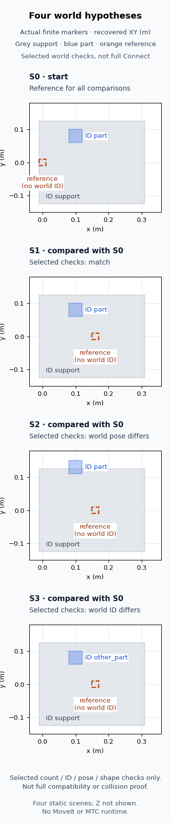
The measured reference displacement was 0.1600000226 m, and the changed part displacement was 0.0499999728 m before table rounding. These are digital-coordinate consistency results, not measured robot accuracy. In the pose-change pair, the largest absolute difference among the object-matrix elements was about 0.0462248 after the common rotation. A matrix-element comparison and a three-dimensional center distance are different quantities; neither is a physical safety margin.
The important distinction is visible without a planner. Moving only the planned reference leaves the selected world fields unchanged. A visually plausible target can still accompany a different part pose, or an identically positioned part under a different ID. In a real task, inspect the actual paired scene objects and their identifiers before treating an empty connector as evidence that a motion planner needs different parameters.
This comparison did not instantiate MTC InterfaceState objects, initialize MTC stages, call Connect, compare robot joint variables, or test attached-body ownership. It did not run MoveIt, ROS, IK, trajectories, sensing, collision checking, physics or hardware. The prisms and authored IDs are explanatory stand-ins. Passing the selected world checks leaves the unmodeled compatibility and planning conditions unresolved. The figure shows common-frame XY projections; the independent check also used the captured three-dimensional geometry.
Stop at the first handoff that lacks evidence
For a missing complete task, work outward from the last successful stage. Name the interface it writes and the neighbor that reads it. Follow the linked state and solution, verify the exact monitored source where applicable, inspect the two world hypotheses, and trace each required property’s configured source. Only after those boundaries have evidence should planner tuning become the next question.
If the state pair passes the selected world checks, continue with the attached bodies, remaining joint variables, planning groups and actual planner result for your task. If the world IDs or poses differ, resolve that scene-hypothesis discrepancy first. Neither a target marker nor an isolated successful stage proves that the complete serial chain exists.