At 45°, my narrow flat follower was positioned at the same authored support-plane height as the wider follower, but the cam’s actual supporting edge landed about 5.16 mm beyond the narrow face. Doubling the face width from 20 mm to 40 mm changed that signed lateral margin to about +4.84 mm. The cam, phase, follower height, depth, and thickness stayed the same; only finite face width changed.
That comparison exposed the modeling error I wanted to test. An infinite plane can sit at the correct cam support height while the finite follower face misses the feature that defines that height. A flat-faced follower model therefore needs two checks: the normal relation to the supporting plane and the support feature’s position inside the finite face boundary.
I made three independently authored static cells in an AI-operated Blender 5.2.2 LTS session on October 9, 2026 KST. This was a virtual finite-geometry experiment, not a physical cam, a working follower, or a continuous contact simulation.
The supporting plane is infinite; the face is not
A common construction places a flat follower on a plane tangent to the cam profile. That is a useful starting condition. It establishes a normal height, but an infinite plane has no lateral edge. The actual follower does.
In this experiment the follower’s working face was a finite rectangle. Its width lay along X, its 16 mm depth lay along Z, and its normal pointed downward along Y. The cam’s highest feature in that normal direction had to project inside both finite face spans. A support feature outside the X range could still define the same infinite supporting plane while missing the physical rectangle entirely.
The Carnegie Mellon University cam mechanism chapter, checked on October 8, 2026 UTC, provides the limited mechanism context: flat-faced followers are a recognized follower form, and a working mechanism needs the follower and cam profile to remain related. The source does not supply my polygon, dimensions, phase, face width, or result. It also does not turn this static boundary construction into maintained physical contact.
Three cells isolate phase and width
The cam was a closed prism whose XY outline used 64 authored samples from semiaxes of 35 mm and 20 mm. It was 12 mm deep along Z. Although the samples came from an ellipse formula, the Blender solid was the resulting 64-sided polygonal prism, not an exact smooth ellipse. Its supporting feature must therefore be recovered from the actual facets and vertices rather than from the analytic support equation of an ideal ellipse.
Each follower was a closed rectangular prism, 6 mm thick along Y and 16 mm deep along Z. The narrow face was 20 mm wide; the wide face was 40 mm wide. In the 0° cell, the narrow follower’s lower face was authored at Y = 20 mm. In both 45° cells, the lower face was authored at approximately Y = 28.493 mm. Those heights were design references computed before construction, not measured follower equilibria under gravity or a spring.
The profile points were (35 cos t, 20 sin t) in millimetres, with t = 2πi/64 for i = 0 through 63. I extruded that polygon from Z = −6 to +6 mm and rotated the whole cam about Z. In each cell’s own frame, the follower was centred at X = 0 and Z = 0, with its centre 3 mm above the authored lower-face height. This keeps the face-width comparison reproducible without substituting a smooth ellipse for the actual mesh.
The first cell paired the narrow follower with the 0° cam. The second paired that same 20 mm width with the 45° cam. The third kept the 45° cam, height, thickness, and depth unchanged while increasing width to 40 mm. Across the two 45° cells, width was the isolated variable.
I recovered the actual follower face from all four evaluated corners and the actual cam support feature from the complete evaluated outline. The maximum feature was an axial edge of the closed faceted cam. That edge relation is important: it is not a positive-area patch and does not by itself prove force-bearing contact.
The support stayed, ran off, and returned
The signed lateral margin measures how far the support feature lies inside the nearest X edge of the follower face. Positive means inside; negative means outside. The axial margin checks the Z span separately. The normal-plane result stayed within the model’s numerical boundary band, so I report it as boundary support rather than physical contact.
| Case | Cam phase | Face width | Actual finite-face result | Reader measurement |
|---|---|---|---|---|
| Narrow control | 0° | 20 mm | support inside face; numerical plane boundary | lateral margin about +10.00 mm |
| Narrow at 45° | 45° | 20 mm | support strictly outside finite face | lateral margin about -5.16 mm; whole solids 0.41–0.42 mm apart |
| Wide at 45° | 45° | 40 mm | support inside face; numerical plane boundary | lateral margin about +4.84 mm |
The 0° narrow case placed the support edge near the middle of the face, leaving about 10 mm to the lateral boundary and about 2 mm to the axial boundary. At 45°, the cam support shifted laterally. With the 20 mm face, the actual signed margin became approximately -5.16 mm. The support plane was still at the authored height, but the support edge was outside the finite rectangle.
The wide 45° case restored finite-face coverage. Its support feature was about 4.84 mm inside the lateral edge and about 2 mm inside the axial edge. Because the two 45° cam meshes, pose heights, and face depths matched, this change came from the 20 mm increase in follower width.
These three rows do not define a minimum working width through a cam cycle. They show that one static phase could distinguish the narrow and wide faces even when both were placed at the same nominal support-plane height.
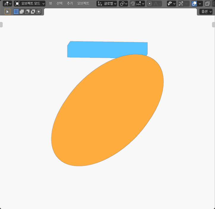
The image shows the actual wide 45° SOLID-editor cell. The other two cells were measured outside the frame. Some interfaces are occluded by the opaque bodies; the support-edge and signed-margin results use complete evaluated geometry rather than visible pixels.
Boundary support is not physical contact
In the 0° and wide 45° cells, the actual support edge lay inside the finite follower face. The cam’s maximum normal coordinate and the follower plane coincided within the 8 micrometre comparison band. I call this a numerical plane boundary, not contact.
A physical contact claim would require more than coincident boundary geometry. This model had no guide, spring, gravity load, contact solver, compliance, force, pressure, friction, or material deformation. It did not establish that a follower would remain pressed against the cam, transmit a load, or form a positive-area pressure patch. The actual supporting feature was a line-like axial edge of a faceted prism, not a measured contact area.
The distinction also prevents a misleading interpretation of the wide-face result. A positive +4.84 mm lateral margin says the edge projected within the rectangle. It does not say the width is recommended, sufficiently stiff, tolerant of manufacturing variation, or safe over a full cycle.
This is a different question from my roller-follower base-radius experiment. That work followed a roller through a full harmonic cycle and compared base radius with pressure angle. Here there is no roller, no pressure-angle target, and no full turn. The decision is whether a particular faceted cam support feature falls on a finite flat face at three static conditions.
Projection deficit and solid distance are different
The narrow 45° cell needs one more distinction. Inside the finite face window, the cam profile’s highest available point sat about 0.4264 mm below the infinite support plane. This is a face-normal projection deficit after clipping the cam to the follower’s finite lateral and axial spans.
It is not automatically the shortest Euclidean distance between the two complete solids. The closest pair can involve the follower’s lower corner and a cam boundary feature outside the working-face window. A separate full-solid calculation bounded the actual distance between approximately 0.415834 and 0.415875 mm. I report that as an outward-rounded 0.41–0.42 mm interval, not an exact global minimum.
The two values are close because of this particular geometry, but they arise from different questions. The 0.4264 mm deficit asks how far below the support plane the best in-window cam point sits. The 0.41–0.42 mm bound asks how close any finite points on the closed cam and follower solids come. Treating one as the other would make the method fail on a different corner or profile.
The same caution applies to negative lateral margin. A support feature outside the working face is a runoff classification in this authored static model. It is not, by itself, positive-volume collision, force loss, damage, or proof that a real mechanism cannot operate with another guide or retention architecture.
A practical finite-face sizing check
Start by recovering the actual follower face, its normal, and its two finite spans. Then find the cam’s maximum feature in that normal direction from the actual captured geometry. Do not replace a faceted profile with an ideal smooth curve unless the ideal calculation is clearly labeled as a separate approximation.
Project the support feature into the follower’s face coordinates. Record the lateral and axial signed margins separately. A positive pair supports a finite-face containment statement; a negative margin identifies which edge was crossed. If the normal gap lies inside the numerical band, preserve a boundary classification rather than calling it physical contact.
When the feature lies outside the face, compute any support-window deficit as a projection quantity. If whole-solid clearance matters, run a separate finite distance check with a certified separation bound and a real boundary witness. Do not reuse the projection deficit as the Euclidean distance.
Finally, repeat the test across every phase required by the design. Three static cells can reveal a failure mode and isolate the effect of width, but they cannot certify continuous support or a full-cycle minimum width. A working design still needs guide and retention geometry, forces, wear, manufacturing variation, dynamics, and physical testing.
For this modeled 45° condition, I would carry the 40 mm face forward to a phase-by-phase coverage check and stop treating the 20 mm face as equivalent. The next check is whether the positive lateral and axial margins survive the required phases and actual guide layout; this static comparison has not answered that question.