A quarter-turn can put a fastener neatly in front of a fixed picker while quietly changing which fastener the process is targeting. I reproduced that failure mode in an actual, AI-operated Blender 5.2.2 LTS experiment with a square board, four distinct embedded heads, and one fixed picker window. All four indexed arrangements were free of cross-component solid intersections. Even so, only the 0° arrangement kept the originally selected head registered with the picker.
That distinction matters more than a clean-looking view. At 90°, a different head occupied the window with the same nominal 2 mm standoff. The originally selected head_plus_Z had rotated to the side. A check based on “the head currently in front” would have accepted the wrong physical target.
Urban Machine describes picking tools that work on four planes of dimensional lumber, along with clamps, vision, gantries, and precision end effectors. I used that architecture only as industrial motivation for the indexing question; the dimensions and fixture below are generic and independently authored. Urban Machine: The Machine
The company also reports a reclaimed-lumber installation that uses cameras, AI, and robotics to locate and remove metal fasteners. That is a vendor account of an installation, not evidence for my model’s quarter-turn sequence, dimensions, or acceptance rules. Urban Machine: Robot Reclaims Lumber
The target must keep its board-local name
The moving assembly had five members: the board and four attached heads named head_plus_Z, head_minus_Z, head_plus_X, and head_minus_X. Those names belong to the board’s local frame. They do not change when the board rotates in the world frame.
I selected head_plus_Z before indexing. At 0°, its outward face points toward the fixed picker. After positive 90° increments about Y, the heads facing the same world-side station were:
- 0°:
head_plus_Z - 90°:
head_minus_X - 180°:
head_minus_Z - 270°:
head_plus_X
The fixed assembly had seven members: four walls around a real empty window, a side bridge, an arm, and a mount. Together, the model therefore contained 12 authored members per state. The board and all four heads moved as one group; the picker stayed fixed.
The board overlapped each head by an authored 1 mm to represent one connected virtual rigid group. Picker members also overlapped where needed to form their connected virtual group. Those same-core overlaps express membership only. They do not prove adhesive strength, a fastener joint, clamping force, or a physical construction method.
For reproduction, the authored 0° bounds below are in millimetres in one common XYZ station frame. The board centre is the origin; +Z points toward the picker. Each head extends 4 mm beyond the board surface and overlaps it by 1 mm. These are input dimensions, not measurements of an industrial machine.
| Member | X interval (mm) | Y interval (mm) | Z interval (mm) |
|---|---|---|---|
| Board | −10 to 10 | −32 to 32 | −10 to 10 |
Original head_plus_Z |
−4 to 4 | −4 to 4 | 9 to 14 |
Original head_minus_Z |
−4 to 4 | −4 to 4 | −14 to −9 |
Original head_plus_X |
9 to 14 | −4 to 4 | −4 to 4 |
Original head_minus_X |
−14 to −9 | −4 to 4 | −4 to 4 |
| Picker left wall | −10 to −6 | −10 to 10 | 16 to 24 |
| Picker right wall | 6 to 10 | −10 to 10 | 16 to 24 |
| Picker front wall | −10 to 10 | −10 to −6 | 16 to 24 |
| Picker back wall | −10 to 10 | 6 to 10 | 16 to 24 |
| Picker side bridge | 8 to 14 | −10 to 10 | 20 to 26 |
| Picker arm | 12 to 18 | 8 to 32 | 22 to 28 |
| Picker mount | 12 to 22 | 28 to 38 | 22 to 32 |
The station’s empty working plane is at Z = 16 mm with X and Y each from −6 to 6 mm. Positive board indexing about Y maps its original +Z side toward +X at 90°; all five board members receive that same rotation about the board centre. The seven picker members keep their station coordinates. I laid the four cells out with shared display translations of (0, 0), (160, 0), (0, 160), and (160, 160) mm in XY, applying each translation to both cores and removing it before measurements. Those display offsets are not extra operating positions.
Four index states gave four different identity results
I authored four separate static cells at 0°, 90°, 180°, and 270°. In every cell, the original head_plus_Z identity remained attached to the same mesh. I then evaluated its complete original outward endcap, rather than relabeling whichever head faced the window.
| Board index | Head facing the picker | Original head_plus_Z result |
All 35 moving-to-fixed pairs |
|---|---|---|---|
| 0° | head_plus_Z |
Fully registered; directed gap about 2 mm | Strictly disjoint |
| 90° | head_minus_X |
Side-on; projected endcap area 0; corner gaps about 12–20 mm | Strictly disjoint |
| 180° | head_minus_Z |
Opposite the station; about 30 mm away and normal reversed | Strictly disjoint |
| 270° | head_plus_X |
Side-on; projected endcap area 0; corner gaps about 12–20 mm | Strictly disjoint |
At 0°, the selected head’s complete 8 × 8 mm working face lay inside the 12 × 12 mm opening. Its four edge margins were approximately 2 mm, its outward normal aligned with the station convention, and all four corner-to-plane gaps were approximately 2 mm. This is a numerical standoff, not contact.
At 90°, head_minus_X produced that registered relationship instead. The green selected head_plus_Z remained the selected physical object, but its original outward endcap was side-on to the station. Its projection onto the working plane collapsed to a line with zero area. The same happened to the selected head at 270°. At 180°, the original face still projected to roughly 64 mm², but it was on the opposite side and its normal pointed away, so it was not registered.
This is why identity, position, and direction cannot be merged into one “near the tool” test. The opposite head at 180° occupied the correct side, while the selected head had the wrong normal and a roughly 30 mm directed gap. At 90° and 270°, the selected face was geometrically edge-on even though another original head fit the window.
The window and the solids answer different questions
The finite-window test considered the complete working face, not only its centre. I used all four endcap corners and edges, projected them into the station plane, and compared the resulting polygon with the complete empty opening. A centre-only check would miss a corner running outside the window. A face-area check without a directed normal would wrongly accept the far-side face at 180°.
I kept whole-solid clearance separate. Every state contained five moving members and seven fixed members, giving 35 cross-core pairs. All 35 were strictly disjoint at every index. Across the four states, the closest evaluated cross-core distance was about 2.828419 mm. I report that as roughly 2.83 mm because the final digits reflect small floating-point residuals in the evaluated geometry; they are not manufacturing resolution or a tolerance recommendation.
| Check | Actual observation | What it establishes |
|---|---|---|
| Stable identity | head_plus_Z remained the original selected mesh in all four states |
The target record did not switch |
| Full face registration | True for selected head only at 0° | The complete face, normal, and 2 mm standoff matched together |
| Finite solid clearance | All 35 cross-core pairs were disjoint in each state | The sampled static arrangement had no moving-to-fixed overlap |
| Indexing path | Four endpoints only | No continuous rotation or first-collision claim |
Clearance therefore did not rescue the wrong-target states. A 90° assembly can be collision-free and show a perfectly registered head while still failing the selected-fastener task. Conversely, the selected object can remain perfectly well defined while no longer being the head available to the picker.
What the Blender view shows—and what it hides
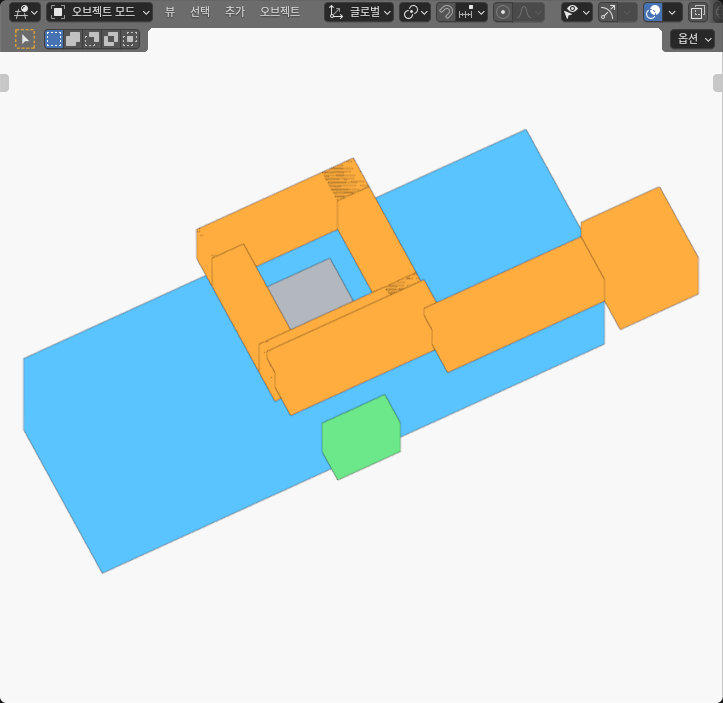
The captured view shows one complete 90° state. The board is blue. The picker ring, bridge, arm, and mount are orange. The originally selected head_plus_Z is green beside the station, while the different head_minus_X appears gray within the ring.
The screenshot is useful because it makes the substitution tempting: a head really does appear where the tool expects one. It is not measurement evidence. Opaque surfaces naturally hide interfaces, and the virtual-union overlaps remain visible only where the view allows. The face registration, zero-area side projections, and 2.83 mm minimum cross-core clearance came from evaluated geometry, not pixels.
The other three measured cells were outside this focused frame without being hidden or deleted. The image was an ordinary whole SOLID editor capture, with no cutaway, transparency, exploded view, labels, crop, or offline render.
A practical target record for indexed work
For a real design review, I would keep four fields together in the target record:
- Immutable component identity. Name the fastener in the workpiece frame, such as board-local
head_plus_Z. - Current rigid transform. Apply the complete board pose to that same member; do not search again for the nearest head after indexing.
- Working-face relation. Recover the transformed face centre, outward normal, complete projected boundary, and signed station gap.
- Whole-assembly clearance. Check every carried member against every fixed member independently of face registration.
If the process intentionally changes to a new head after each quarter-turn, record that as an explicit target transition. If it is supposed to return to the same physical fastener, preserve the original local ID and calculate its current world pose. Color, screen position, and nearest-object selection are weak substitutes for that relationship.
The same separation helps when reviewing a selective tool engagement. My earlier pallet engagement experiment checks a target patch together with retained neighboring members. The mould-opening experiment checks whether an entire carried assembly clears an opening. Here, the distinctive failure is identity: a different attached member can satisfy the station geometry while the requested member does not.
Limits and the design decision
This experiment supports a narrow conclusion: after indexing a multi-sided workpiece, the presence of a compatible head at a fixed station does not prove that the originally selected fastener is there. The 0° state satisfied identity, complete-face registration, normal direction, numerical standoff, and whole-solid clearance together. The 90°, 180°, and 270° states retained whole-solid clearance but failed the original-target registration check.
The study used four independent static poses. It did not simulate continuous indexing, find the first intermediate collision, extract a fastener, grip wood, measure force, evaluate vision, run a controller, or test hardware. The board, heads, and picker are generic closed solids rather than vendor CAD. The model also says nothing about wood damage, tool compliance, process time, recovery logic, metal-free certification, or safety.
The actionable decision is simple: choose whether the station follows a physical fastener identity or merely services the currently presented side. Then encode that choice in the workpiece frame before checking face fit and clearance. A collision-free pose and a head inside the window are necessary geometric facts, but they are not a substitute for knowing which head the process is about to act on.