Moving a divider clear of a conservative gripper approach box did not make the target visible to the camera. In layout B, the box had 100 mm of clearance from the divider, but all 25 sampled sightlines to the cube’s top face remained blocked. Moving the divider behind the cube in layout C kept the same 100 mm clearance and left all 25 sightlines unblocked.
This was a virtual layout study operated by Codex in Blender 5.2.2 LTS on October 4, 2026. It used one cube, two bins, and a simplified stationary gripper to examine a proposed tabletop sorting arrangement. No robot was built or operated, and no AI recognition or grasping test was performed. The useful result was a distinction between two layout checks: room for an approach and an unobstructed view of the target.
One divider, three positions
The opaque divider was introduced as a controllable obstacle. It was not a required component of a real sorting machine. Its dimensions stayed unchanged, and only its position along the Y axis varied: −60 mm for A, −200 mm for B, and +200 mm for C.
The downloadable scene and measurement records preserve the conditions. Coordinates below are in millimetres, with the tabletop surface at Z = 0. The observation camera sits on the negative-Y side of the cube, so moving the divider toward negative Y moves it toward the camera.
| Condition | Fixed value |
|---|---|
| Work surface | 700 × 640 mm |
| Target | 60 mm cube, centred at (0, 0, 30) |
| Observation camera | (0, −850, 640), aimed at (0, 0, 70), 50 mm lens |
| Divider | 500 × 20 × 220 mm; X = 0, Z = 110 |
| Assumed gripper approach | 200 mm vertically downward; no motion executed |
| Rendering | Cycles, 32 samples, seed 17, 1280 × 960, AgX |
The cube, bins, gripper starting pose, camera, lighting, and materials stayed fixed. The provided scene uses basic geometry rather than a product-specific gripper model. The three comparison images below use the same observation camera.
B cleared the approach box and still hid the cube
A placed the divider close to the target. It occupied part of the volume reserved for the assumed downward approach and hid the cube from the observation camera. The signed approach-box clearance along Y was −40 mm, and all 25 sampled sightlines were blocked by the divider.
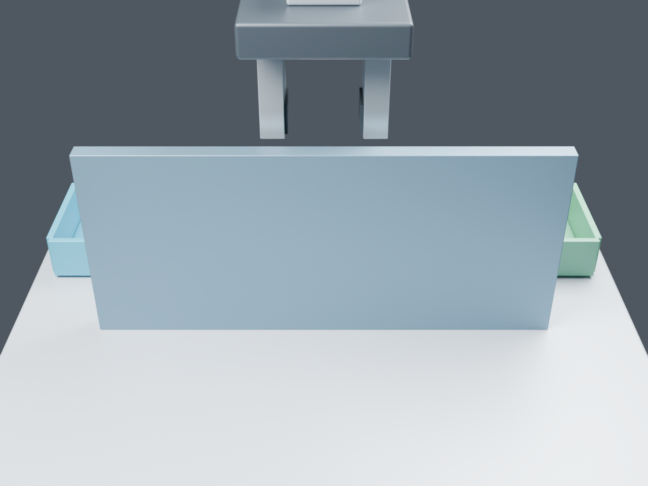
B moved the divider toward the camera, to Y = −200 mm. That move put 100 mm between the divider and the approach box along Y. It did not change the divider’s height or remove it from the camera-to-target sightlines. The cube remained hidden.
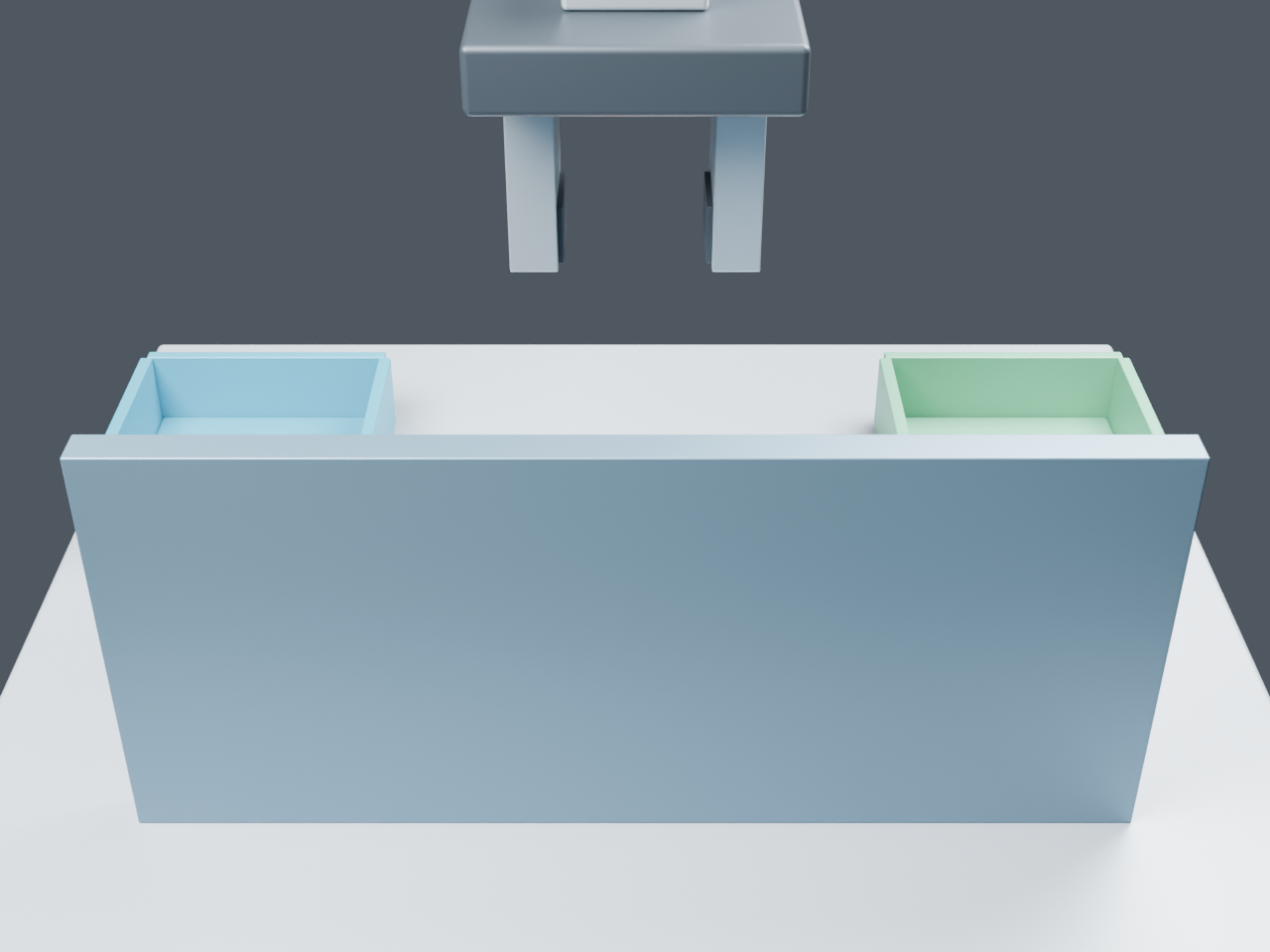
B is worth keeping in the comparison because it separates the two outcomes. It removed the approach-box overlap without improving the measured view. A comparison containing only A and C would lose that result.
For C, the same divider moved to Y = +200 mm, behind the cube as seen by the camera. The Y clearance matched B’s, while the divider’s relationship to the camera changed. All 25 sampled sightlines were now unblocked.
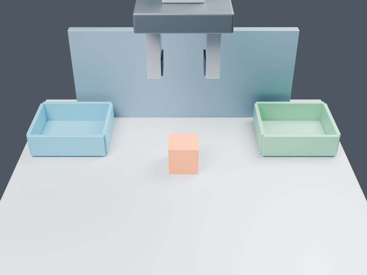
The individual measurement records preserve both results for every placement:
| Layout | Divider Y | Unblocked top-face sightlines | Signed approach-box clearance along Y |
|---|---|---|---|
| A | −60 mm | 0 of 25 | −40 mm |
| B | −200 mm | 0 of 25 | +100 mm |
| C | +200 mm | 25 of 25 | +100 mm |
What the two measurements actually count
The sightline test sampled a 5 × 5 grid inside the cube’s top face at Z = 60 mm. The X and Y coordinates each ran from −24 to +24 mm in 12 mm steps. The measurement script checked finite lines from the observation camera to those points for intersections with the evaluated physical meshes, excluding the target itself. The divider was the first blocking object for every sampled line in A and B. Blender’s BVH ray-cast API supports a maximum ray distance; the recheck code transforms each camera-to-point segment into the tested object’s coordinate frame before testing it.
A separate projection and settings check confirmed that all 25 points lay inside the observation camera’s frame and clipping range in each layout. It also recorded matching selected geometry and settings across A, B, and C, with the divider’s Y position excluded from the comparison. The projection uses Blender’s world-to-camera conversion, with clipping checked separately. That is a check of the recorded properties, not a guarantee that every possible Blender property was identical. The API documentation was checked on October 5, 2026.
A result of 25 of 25 means those 25 sightlines were unblocked. It does not measure recognition accuracy, the visible percentage of the cube, or visibility of its other faces and edges. No detector or pose estimator was evaluated.
The approach box was a conservative volume around an assumed 200 mm vertical descent. It extended 90 mm either side of the target in X and Y, adding 10 mm to the gripper’s maximum horizontal half-width. Its Z range was 12.5–412.5 mm. The gripper stayed in its starting pose; the box included empty space as well as the space reserved for its descent.
For this axis-aligned geometry, the recorded signed Y clearance was calculated as:
|divider Y| − 10 mm − 90 mm
Here, 10 mm is half the divider’s thickness and 90 mm is the approach box’s half-width along Y. With the X and Z ranges overlapping, a negative result indicates approach-box overlap and a positive result indicates separation along Y. The −40 mm value is this signed geometric measure; it is not a measurement of actual finger contact. The +100 mm result is not a certified safety distance.
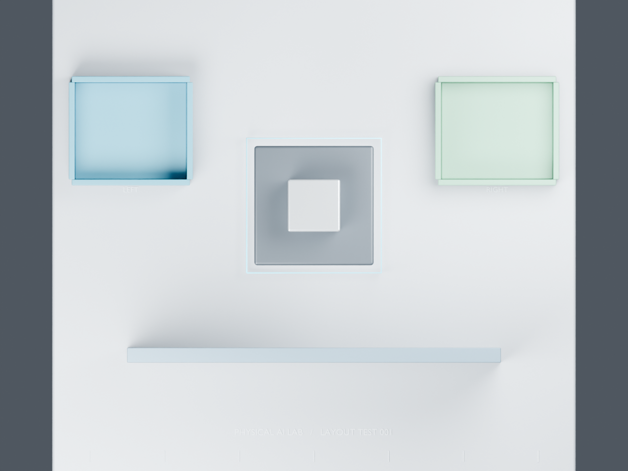
In this overhead image, the stationary gripper obscures the cube below it. It is a diagnostic view, not a substitute camera-visibility result.
Use C for the next layout check
C is a candidate starting point for the next test because it met both limited checks in this scene. It is not evidence of a successful sorting cycle. No arm base, joints, reach limits, transport path, dynamics, or hardware performance were evaluated.
To inspect the result, download the Blender scenes, measurement records, and recheck script. Extract the ZIP, open layout-study.blend, then open recheck_l001.py in Blender’s Text Editor and run it. A new timestamped folder receives results.json; the script does not save the scene file or rerender the images. The public scene export was opened and the script was run in Blender 5.2.2 LTS on October 5: it reproduced the three sample counts and signed margins above.
For a similar layout review, keep the two measurements separate as the design becomes more detailed:
- Check small position changes around C. Keep the observation camera fixed and record both sampled occlusion and approach-box clearance for each divider position. This would locate the boundaries that the three placements do not establish.
- Replace the box with the actual gripper motion. Define finger length, opening width, and grasp pose, then check the modeled geometry throughout approach and closing. The box result alone cannot decide whether that motion works.
- Add the route to the bins. Include the arm’s links, joint limits, and pick-to-place path before assessing interference across a full cycle.
- Measure perception separately. Use camera images and ground truth to test detection or pose estimation, including failures. Clear sampled sightlines supply no recognition score. A 2D target point also needs its own coordinate and control interpretation before it becomes a robot action.
The immediate layout decision is to carry C forward for those checks and retain B as the counterexample: clearing the proposed approach volume did not, by itself, expose the target to the camera.