A four-bar admits a complete ideal crank revolution when its links can close at every input angle. Keeping its two assembly branches distinct throughout the revolution is a stricter requirement. With an 80 mm ground link and 20 mm crank, the 60/50 mm coupler/rocker pair passes both checks. The 40/40 mm pair has an impossible angle range. The 50/50 mm pair closes at every angle, but its branches meet at 180°.
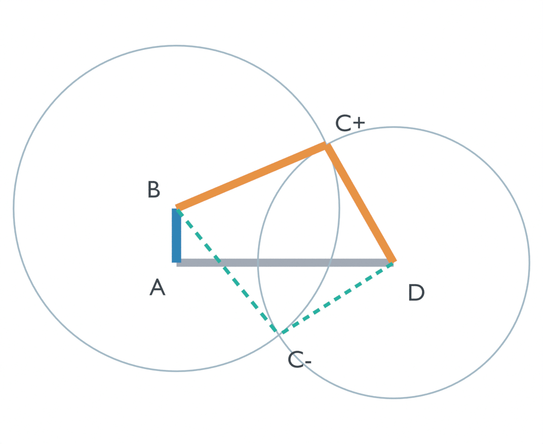
Check the distance swept by the crank pin
Call the ground length g, crank radius r, coupler length b, and rocker length c. Put A at (0, 0), D at (g, 0), and measure the crank angle θ from the ground line. The crank pin is:
B = (r cos θ, r sin θ).
The coupler–rocker joint C must lie on both a circle of radius b centered at B and a circle of radius c centered at D. Their center distance is:
d(θ) = √(g² + r² − 2gr cos θ).
Over a complete turn, d ranges from |g − r| to g + r. Here, that means 60 ≤ d ≤ 100 mm. For these separated circle centers, the pose has two distinct intersections when:
|b − c| < d < b + c.
At equality, the circles touch and the two joint positions coincide. Beyond a boundary, no real joint exists. Two distinct assemblies throughout the turn therefore require:
|b − c| < |g − r|, and b + c > g + r.
For 60/50 mm, the difference is 10 mm and the sum is 110 mm. Both inequalities hold across the 60–100 mm range. The minimum 10 mm feasibility margin is the surplus coupler-plus-rocker length over the largest center separation.
Three link pairs give three different answers
We swept each pair through 721 prescribed positions, from 0° through 360° in 0.5° increments. The table counts the 720 unique input angles; 360° repeats 0°.
| Coupler / rocker | Two distinct assemblies | Tangent poses | Impossible poses |
|---|---|---|---|
| 60 / 50 mm | 720 | 0 | 0 |
| 40 / 40 mm | 331 | 0 | 389 |
| 50 / 50 mm | 719 | 1 | 0 |
For a motor required to turn the input continuously, the 40/40 mm geometry cannot deliver a whole revolution under these rigid-link assumptions. An oscillating input may still suit a task whose required arc fits within the feasible range. Full rotation is a task requirement, rather than a score that every useful linkage must maximize.
The 40/40 mm links can span at most 80 mm between B and D. Substituting that limit into the distance equation gives cos θ ≥ 1/8, so closure exists over:
0°–82.819244° and 277.180756°–360°.
At both endpoints the circles touch. Neither endpoint lands on the half-degree grid, which explains the table’s zero tangent count. The sampled feasible share is 331/720, or about 45.97%; the continuous angular share is about 46.01%. A sampling result alone would miss the two exact tangencies.
For 50/50 mm, the maximum span is exactly 100 mm. At 180°, B is at (−20, 0), C at (30, 0), and D at (80, 0), in millimeters. Every input angle has a closure, but this collinear pose has only one distinct C position.
Apply Grashof with the fixed link in mind
Carnegie Mellon University’s planar-linkages chapter gives Grashof’s criterion as s + l ≤ p + q, using the shortest, longest, and two intermediate links. Its classification also depends on which link is fixed and where the shortest link sits.
Our 20 mm input is the shortest side link and the 80 mm ground is fixed. The three sums are 100 < 110, 100 > 80, and 100 = 100: the strict crank-rocker, double-rocker, and change-point equality cases respectively. “Grashof satisfied” alone hides the strict/equality distinction. Keep the ground and input explicit to determine which link can revolve.
Choose an assembly, then watch where it meets the other
The two circle intersections are alternative assemblies of the same dimensions. Denote their joint positions C+ and C−. Away from tangency, select the starting assembly and track its position as the input advances. An animation that selects a fresh solution independently at each frame can jump between assemblies.
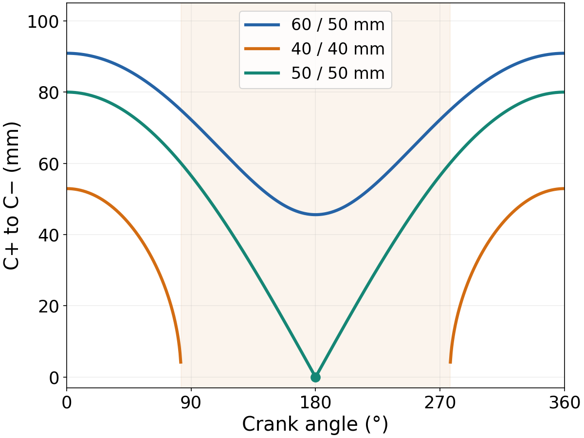
At the 50/50 mm meeting, both branch labels describe the same position. Position continuity alone cannot uniquely select the continuation there; a smooth traversal can exchange the algebraic branch sign. Flag this pose explicitly when building a trajectory.
CMU defines a change point as simultaneous alignment of all four bars. That describes the 50/50 mm pose at 180°. At the 40/40 mm range limits, the coupler and rocker align while the crank remains off their line. The 60/50 mm case also has crank–coupler alignments at rocker reversals, with its two C positions still separated. These different alignments should retain their different meanings.
What the Blender sweep establishes
This October 5, 2026 study used Blender 5.2.2 LTS, operated by Codex through Blender MCP, with prescribed circle-intersection geometry. Both branch labels at all 721 angles produced 4,326 records. Impossible joints and their bar readings were left null. Closure status used the intended dimensions in double precision; mesh coordinates were measured separately so coordinate rounding could not turn exact equality into an artificial branch gap.
The first sweep classified closure using Blender’s rounded coordinates. At the intended 180° equality, a tiny coordinate shift made the 50/50 mm case appear to retain two distinct branches. We rejected that result and reran classification from the specified dimensions, while keeping mesh measurements as a separate check. For a design exactly on a boundary, decide what dimensions define the test before interpreting a tiny apparent gap.
An independent reconstruction checked both branches. Maximum measured bar-length residual was below 0.00003 mm, and joint-coordinate discrepancy below 0.000034 mm, within a 0.0001 mm numerical tolerance. These are software consistency checks, not fabrication tolerances. The sweep included no dynamics, contact, forces, motor, or hardware test, so it establishes geometric closure rather than loaded performance.
For your chosen lengths, check both ends of the full d range and preserve strict inequality if separated branches are required. Once that geometry passes, motion timing is a separate decision; our slider-crank and Scotch-yoke endpoint comparison examines how geometry changes the time spent near a translating output’s endpoint.