Changing an open belt to a crossed layout does more than reverse a shaft. With the same 30 mm and 15 mm pitch radii at 120 mm centers, the smaller pulley’s ideal wrap increases from 165.64° to 224.05°. The straight spans also acquire an intersection, 80 mm from the large-pulley center. Moving the shafts farther apart reduces the crossed wrap angle but does not remove that crossing in the shared plane.
Those are geometric results from six static Blender constructions, not a recommendation to cross a particular belt. For a robot transmission, the useful decision is whether the desired rotation direction, pulley engagement and physical route can all be satisfied. A large wrap angle answers only one of those questions.
Start with direction, then draw the actual tangent paths
The IIT Kharagpur introduction to belt drives distinguishes two arrangements: an open belt gives the pulleys the same rotation direction, while a crossed belt gives opposite directions. That direction relationship assumes the belt transmits motion; this experiment does not simulate friction, slip or torque.
An open path uses external common tangents: each straight span touches both circles on the same side. A crossed path uses internal common tangents: each span touches opposite sides of the two circles. Connecting arbitrary points that look plausible in a drawing is insufficient. At a genuine tangent endpoint, the pulley radius and the straight span are perpendicular.
Our fixture uses ideal circular pitch paths with R = 30 mm, r = 15 mm, and center distance C = 120 mm. A pitch radius describes the chosen belt centerline around a pulley; it need not equal a real pulley’s outside radius. Actual belt thickness and pulley geometry would have to be included when translating these dimensions into hardware.
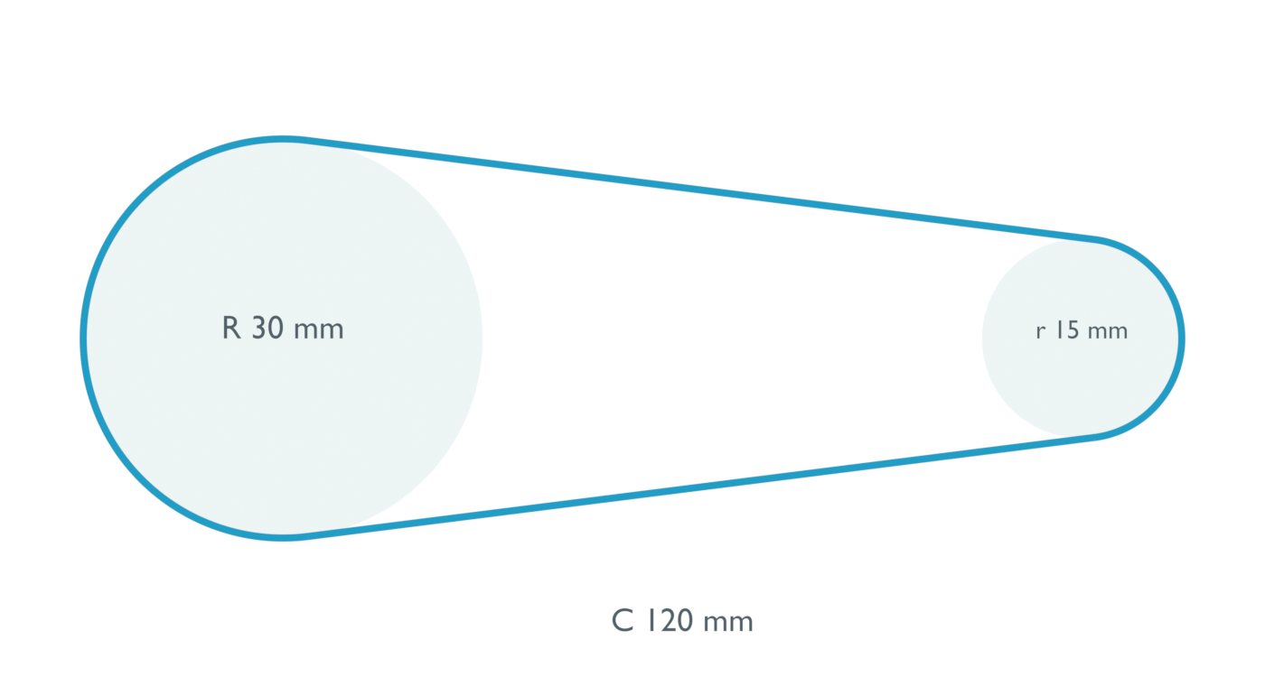
For the open layout, the tangent right triangle contains the radius difference. Define β = asin((R − r)/C). The smaller pulley’s wrap is 180° − 2β, and each straight span has length √(C² − (R − r)²). The fixture gives 165.64° of wrap and 119.06 mm per straight span. That span length is not the length of the entire belt: the two pulley arcs must also be included.
Why crossing increases wrap and creates an intersection
For internal tangents, the corresponding right triangle contains the radius sum. Thus β = asin((R + r)/C), both pulleys have wrap 180° + 2β, and each straight span has length √(C² − (R + r)²). Here the smaller-pulley wrap is 224.05°, while each straight span shortens to 111.24 mm.
This sum-of-radii equation is our geometric derivation. The linked NPTEL PDF’s crossed-angle line on page 5 prints the radius-difference form again. Direct inspection confirms the discrepancy in the printed equation, so we do not use it as authority for the crossed value. Instead, the actual tangent endpoints were checked for radius, perpendicularity and agreement with the sum-of-radii triangle.
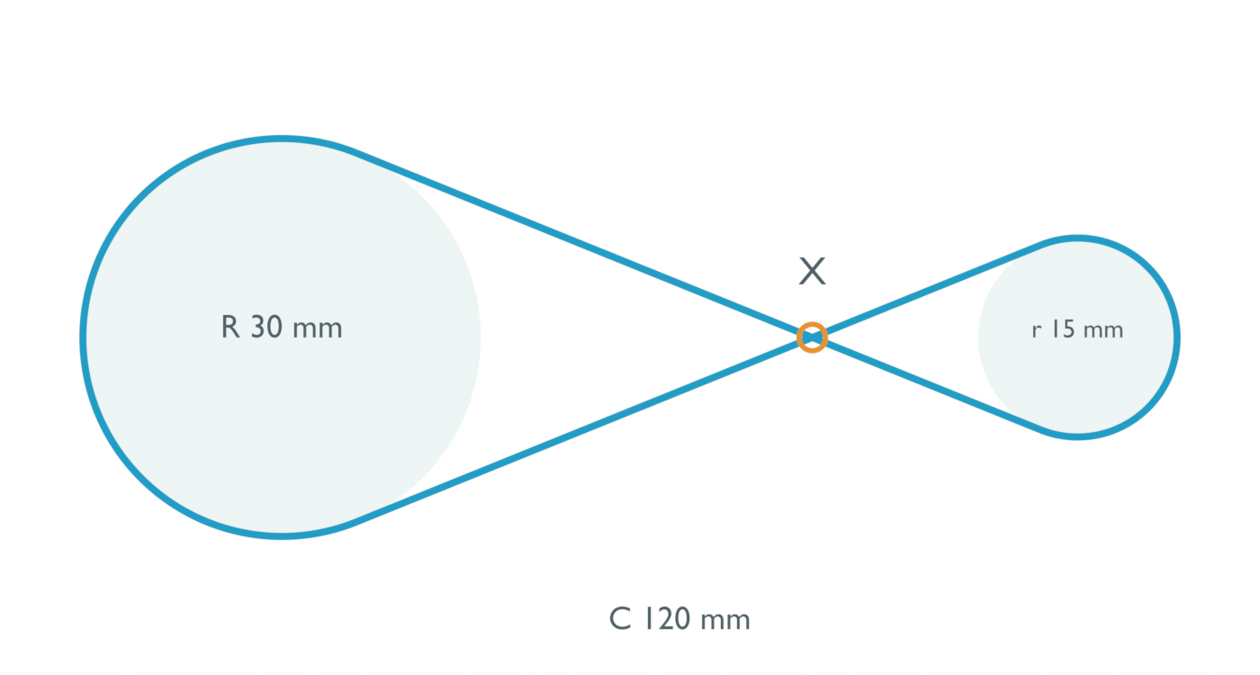
The construction requires C > R + r for separated pulleys and nondegenerate internal tangents. Satisfying that inequality does not establish useful shaft spacing for a working drive. The rendered blue tube gives the zero-thickness path a visible envelope; its 0.55 mm display radius is an illustration, not a selected belt cross-section.
The two centerlines genuinely intersect at X. A finite belt cannot occupy both paths at that point without contact, deformation or a change in the three-dimensional route. The picture does not resolve those possibilities. Its value is to identify the region that needs a routing decision before treating the assembly as interference-free.
More center distance moves the crossing rather than curing it
We held the two radii fixed and constructed both layouts at 90, 120 and 180 mm centers. The following angles come from the displayed small-pulley arc coordinates, rounded to two decimals. Intersection locations refer to distance along the line of pulley centers from the larger pulley.
| Center distance | Open small-pulley wrap | Crossed small-pulley wrap | Crossed intersection location |
|---|---|---|---|
| 90 mm | 160.81° | 240.00° | 60 mm |
| 120 mm | 165.64° | 224.05° | 80 mm |
| 180 mm | 170.44° | 208.96° | 120 mm |
For crossed spans, similar triangles place the intersection at x = C·R/(R + r). With this 2:1 radius ratio, that is two-thirds of the center distance. Both intersection parameters remain between the endpoints in all three cases. Increasing C moves the crossing while the crossed wrap approaches 180° from above; it does not lift one span out of the plane.
Open spans have a different trap for a geometry checker. Their extended lines intersect at x = C·R/(R − r), or twice C for these radii. The corresponding parameter on each segment is 2, outside the actual span’s interval from 0 to 1. A checker that tests infinite lines without checking segment limits would incorrectly report a belt crossing in the open arrangement. Its wrap approaches 180° from below as C increases.
What the experiment verifies before a belt is selected
On October 5, 2026, we used Blender 5.2.2 LTS to create six separate, static scenes. Each contains two pulley disks, tangent endpoint objects and circular contact-path arcs. We read their world coordinates and independently recalculated span lengths, wrap angles and finite-segment intersections. The retained scenes and measurements support reconstruction of this geometric check; they are not a running belt simulation.
The largest radius discrepancy was about 0.0000074 mm, and the largest span discrepancy about 0.0000060 mm. Wrap agreed within 0.0001°. These are numerical readback checks against the intended construction, not machining or assembly tolerances. The model leaves belt tension, sag, elasticity, twist, friction, wear and transmitted power unresolved. The three center distances are illustrative fixtures, not recommended installation dimensions.
The IIT Kharagpur flat-belt design lesson treats material, thickness, allowable stress, speed and wrap corrections as separate design inputs. A wrap increase therefore does not, by itself, prove greater usable torque or longer life. Nor does this circular-path model establish compatibility with a toothed, V-shaped or other specific commercial belt.
For a practical layout, first choose the required output direction and draw the appropriate tangents using the intended pitch radii. Check the small pulley’s wrap and each span’s clearance through its full route. At a crossing, specify how the selected belt and pulley arrangement physically handles that region, then assess the actual section, allowable bend or twist, tension and operating conditions. The same distinction applies to our spur-gear center-distance experiment: a desired transmission ratio and a visually plausible assembly can leave an important engagement or clearance condition unanswered.