The two guide corrections did not add independently in my four-state Blender experiment. Treating the left guide’s 30-degree change and the right guide’s 30-degree change as separate lookup corrections predicted a combined route length of about 217.5430 mm. The measured combined state was 217.3746 mm, so that additive lookup overpredicted the route by about 0.17 mm. The independently propagated mixed-length interval was -0.168435 to -0.168274 mm, which excluded zero for this sampled grid and this explicitly fixed upper route class.
I made the comparison in an AI-operated Blender 5.2.2 LTS session using four independently authored static cells. This was a finite-geometry experiment, not a tendon simulation. It did not run MuJoCable, contact physics, tension, friction, a controller, or hardware.
The useful test is the combined state
Suppose a calibration table stores one correction for rotating the left guide and another correction for rotating the right guide. The tempting model is:
combined length = baseline + left correction + right correction
That model can be tested with four measurements. I used left and right clockings of 0 and 30 degrees, producing L00, L10, L01, and L11. If the corrections add independently on this grid, then L11 - L10 - L01 + L00 should contain zero within the declared numerical bounds.
The measured lengths were:
| Left clocking | Right clocking | Actual upper-route length | Change from L00 | Use in the test |
|---|---|---|---|---|
| 0° | 0° | 214.0792 mm | 0.0000 mm | Baseline L00 |
| 30° | 0° | 214.2729 mm | +0.1937 mm | Left-only state L10 |
| 0° | 30° | 217.3493 mm | +3.2701 mm | Right-only state L01 |
| 30° | 30° | 217.3746 mm | +3.2954 mm | Combined state L11 |
The table is rounded for reading. I did not calculate the decision from those displayed values. The independent check used all four unrounded route-length intervals, then propagated their signs through the mixed expression. That produced the interval from -0.168435 to -0.168274 mm.
Another way to read the same result is to form the additive prediction directly. L10 plus L01 minus L00 gives approximately 217.5430 mm. The actual L11 result was approximately 217.3746 mm. The lookup therefore overpredicted the combined state by about 0.17 mm.
One guide’s response changed with the other guide
The coupling becomes easier to see when the same left-guide change is compared under two right-guide states.
With the right guide at 0 degrees, rotating the left guide from 0 to 30 degrees increased the route by 0.193691 mm. With the right guide already at 30 degrees, the same left-guide clocking change increased it by only 0.025337 mm. The conditional response changed by the same approximately 0.1683546 mm measured by the mixed test.
This happened because the route was reconstructed across both finite profiles at once. The shared span between guides did not have two permanently assigned endpoints. Clocking one profile changed which finite corners supported the exterior chain, and that altered the conditions under which the other profile contributed to the total length.
That is the practical reason to measure the combined state. A pair of single-guide tables can each be internally consistent and still fail when their corrections are added. Before using separate tables, include at least one crossed state in which both guide variables change. Compare its measured route with the sum predicted from the isolated states.
I fixed the geometry and the route class first
Both guides were generic closed affine 24-gon prisms. Each planar profile had a 30 mm X semiaxis and an 18 mm Y semiaxis, with depth extending from -6 to +6 mm in Z. Their centers were 80 mm apart at X = -40 and +40 mm. The route references were fixed at A = (-100, -10) mm and G = (100, -10) mm in the common design plane.
For every state, I used the complete upper exterior support chain from A to G over the union of both guide profiles. Each directed segment had to support all 48 actual planar guide corners, with both guide interiors on its lower side. Both guides also had to contribute to the chain. That definition prevented the calculation from quietly switching to a lower route or treating two unrelated one-guide routes as if they were the shared route.
The four Blender cells were laid out in a two-by-two display grid, but those display translations were removed before measurement. The analysis recovered each guide’s planar corners from its evaluated world geometry, reconstructed the upper chain, and summed its segments. The actual evidence contained 12 closed meshes, 536 evaluated vertices, and 1,024 native triangles across the four static cells. Those counts describe the finite evidence; they are not a claim about model fidelity to a manufactured guide.
The orange route reference was also a closed mesh, but it was deliberately thin and displaced for display. Its section was 0.6 by 0.6 mm and its center was 7 mm above the guide center plane. It was not a cable diameter or a contact surface. Route length came from the guide-derived upper chain. The independently recovered means of the reference ribbon were checked separately rather than substituted for that chain.
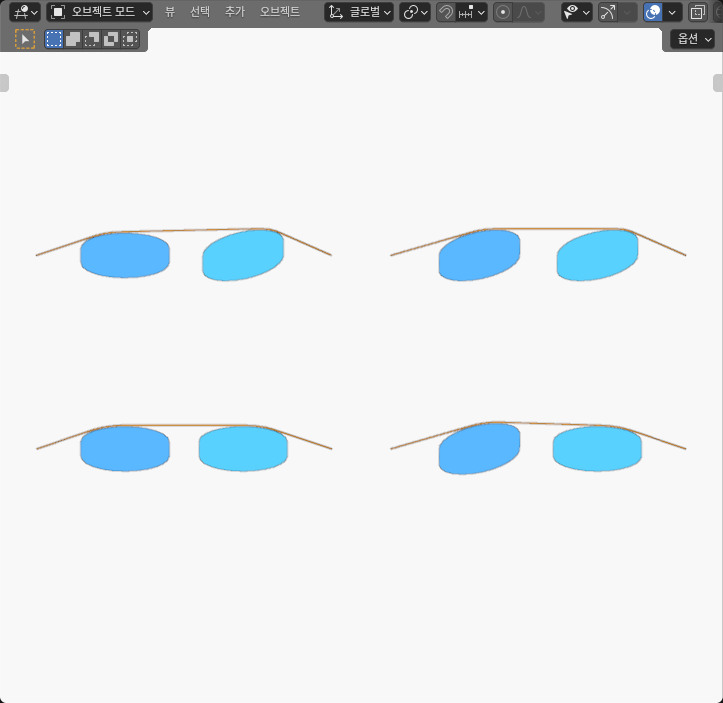
Why the interval matters more than the sign alone
A signed result near zero can be created by rounding, cell-order mistakes, or subtracting values that were already shortened for a table. I kept the cell order explicit: combined minus left-only minus right-only plus baseline. Each route length was bounded first, and the mixed interval was propagated from those unrounded bounds.
The whole interval was negative and stayed away from zero. That supports one narrow conclusion: the additive correction model did not reproduce this four-state finite grid for this upper route class. The negative sign means the separate corrections overpredicted the combined length; it does not mean a tendon must move backward, lose tension, or produce negative torque.
The numerical allowances also are not manufacturing tolerances. They controlled correspondence and comparison of evaluated coordinates in this authored model. They do not prescribe machining clearance, cable stretch allowance, calibration resolution, or an acceptable transmission error.
This distinction is especially useful when a small mixed term is being compared with a design budget. Use outward bounds from the full-precision measurements. Then compare the whole interval with the allowed route-length error. A rounded “0.17 mm” should not be treated as either an exact value or an automatic failure threshold.
This extends the single-guide check
My earlier single-guide route-length experiment asked whether one fixed angle-to-length slope represented three sampled clockings of one noncircular guide. The result here answers a different question. Even after each guide has its own correction, can those two corrections be added when both guides share one exterior route?
The source motivation is similarly narrow. MuJoCable v2, revised September 10, 2026, describes configuration-dependent surface-constrained cable routes and route length in Sections 3.2 and 3.3. That supports measuring a complete route instead of assuming a fixed mapping. It does not supply my paired 24-gon geometry, the four-state mixed test, the Blender measurements, or the nonadditive result. I did not execute its plugin or reproduce a paper benchmark.
For a real mechanism, I would keep the single-guide and paired-guide checks as separate calibration questions. First confirm that each one-variable table resolves the desired range. Then add crossed states that exercise both variables. If a crossed state falls outside the additive prediction interval, use a joint lookup, recompute the complete route from geometry, or restrict the operating region. The right choice depends on the permitted error and on whether the route class remains stable.
What this experiment does not establish
These are four static samples at 0 and 30 degrees. They do not define a local mixed derivative, a Jacobian, or a continuous two-angle law. A route transition could occur between samples, and another exterior class could behave differently. The regularity of the finite 24-gon profiles does not turn them into smooth analytic ellipses.
The experiment also did not model a flexible tendon contacting a surface. It measured closed guide geometry and one declared support chain. It says nothing about friction, slack, stretch, tension distribution, payout, force, torque, wear, controller behavior, or safety. The ideal exit G is a geometric reference with an unmodeled free tail, not a second fixed material endpoint.
The result is still actionable. If two guide variables are going into one calibration, do not validate only the two isolated axes. Freeze the route class, measure the whole finite geometry at crossed states, retain unrounded intervals, and test the combined state against the sum of the separate corrections. In this model, that check found a small but resolved 0.17 mm overprediction that two one-guide lookups would have missed.