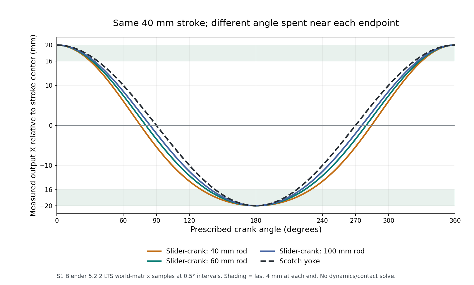
Choose a slider-crank or Scotch yoke by the motion your load needs, not only the stroke length. In our Blender comparison, both produced a 40 mm stroke from a 20 mm crank radius. With a 60 mm connecting rod, the slider-crank spent about 17.9% of its sampled cycle in the last 4 mm at one end and 24.6% at the other. The Scotch yoke spent about 20.4% near each end. Equal travel did not give equal time windows.
That difference matters when a motor-driven pusher needs time close to a placement or inspection position. It does not establish which mechanism can carry the load, run efficiently, or last longer. This was a prescribed geometric motion study in Blender 5.2.2 LTS, operated by Codex through Blender MCP on October 5, 2026. No motor, controller, friction, contact force, or hardware was tested.
First decide what “near the end” means
Here, the useful window was the last 4 mm of a 40 mm stroke: output X at or above +16 mm, or at or below −16 mm, relative to the stroke center. That is a position threshold, not a period in which the output stops. Neither mechanism has a finite stationary dwell under continuous constant-speed crank rotation in this ideal model.
For a pusher that must stay within a placement tolerance, substitute that tolerance for 4 mm. For an inspection task, establish the permitted motion during exposure. A generous near-end zone can look useful on a plot while still allowing too much movement for the actual task.
We sampled each mechanism at 721 crank positions from 0° through 360°, in 0.5° steps. The repeated 360° pose was excluded when counting fractions of a cycle. Equal angle steps represent equal time steps only if the crank speed is constant. A servo that deliberately slows or stops the crank changes that timing problem.
A connecting rod changes the shape of the travel
The slider-crank places a fixed-length rod between the rotating crank pin and an output constrained to a straight guide. At the quarter-turn, the pin is off the guide axis, so part of the rod length spans the lateral offset. The output is already past the stroke midpoint even though the crank’s horizontal projection is zero.
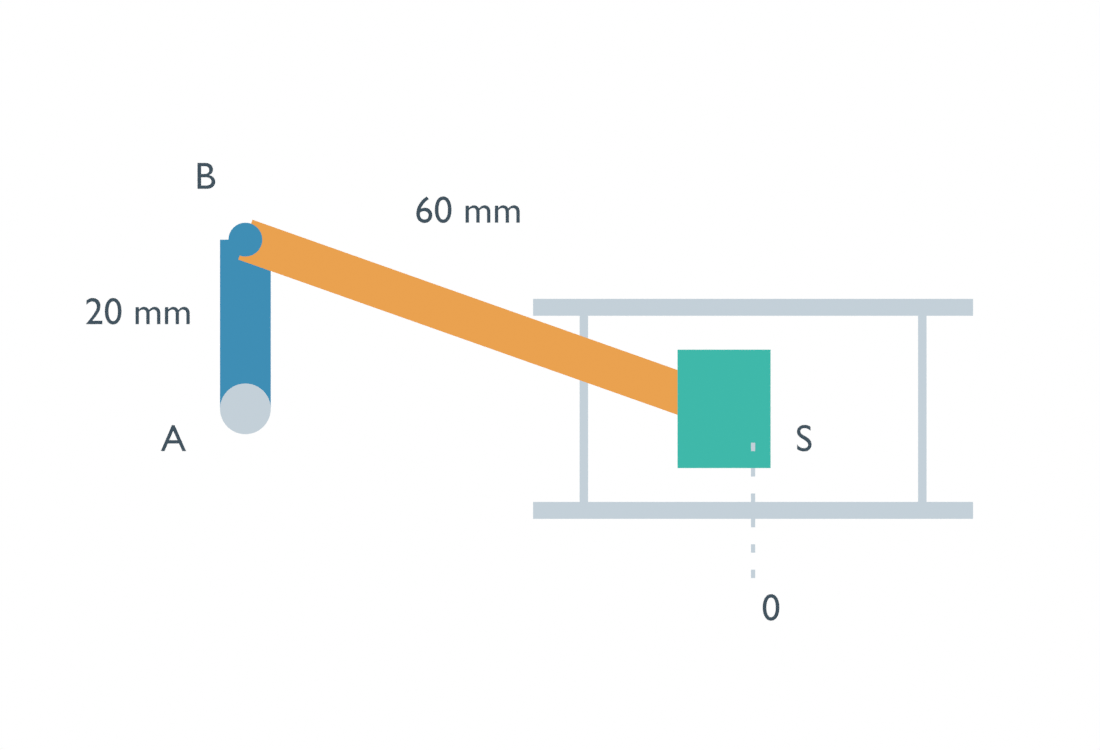
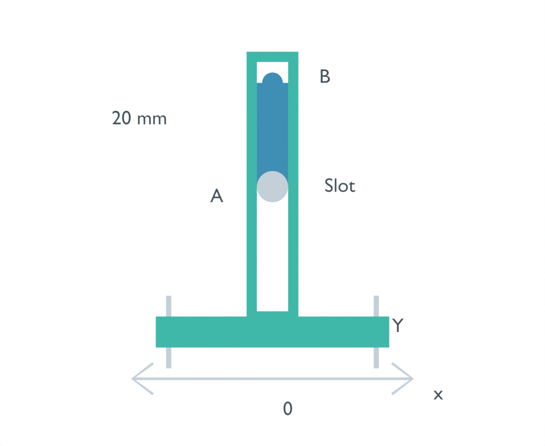
With the 60 mm rod, the measured output at 90° was X = −3.43 mm relative to its stroke center. For the Scotch yoke, it was effectively 0 mm. The yoke follows the crank pin’s horizontal projection through a transverse slot, giving a sinusoidal position profile. The University of Florida’s dynamics notes explain that projection relationship; choosing sine or cosine simply changes the angle origin.
We also changed the rod length to 40 and 100 mm. Those are comparison conditions within this one drive-selection question, not separate proposed products. All three slider-cranks retained the same stroke, while the endpoint time split moved closer to the yoke’s symmetry as the rod became longer.
| Mechanism | Samples near +20 mm end | Samples near −20 mm end | Sampled cycle fractions, + / − |
|---|---|---|---|
| Slider-crank, 40 mm rod | 121 of 720 | 197 of 720 | 16.81% / 27.36% |
| Slider-crank, 60 mm rod | 129 of 720 | 177 of 720 | 17.92% / 24.58% |
| Slider-crank, 100 mm rod | 135 of 720 | 163 of 720 | 18.75% / 22.64% |
| Scotch yoke | 147 of 720 | 147 of 720 | 20.42% / 20.42% |
These percentages count sampled poses. An independent exact-angle calculation gave 17.82% and 24.50% for the 60 mm rod, and 20.48% at either end for the yoke. The small difference is the half-degree sampling boundary. It is not a claim about a real actuator’s timing precision.
Check closure before trusting the animation
Blender did not discover the linkage motion through a contact solver. We prescribed ideal poses, updated the scene, and read the output’s world coordinates and the rod mesh endpoints. The Blender scene uses meters with a unit scale of 1; the records and article report millimeters. Frame 181 represents 90°, and playback at 24 fps is only a visualization setting.
For an inline slider-crank on the positive assembly branch, the position used to construct the poses was:
x = r*cos(theta) + sqrt(L*L - r*r*sin(theta)*sin(theta)) - L
yoke_x = r*cos(theta)
r = 20 mm; L = 40, 60, or 100 mm
Subtracting L sets the stroke center to zero. The crank pivots were shifted by −L in the scene so all outputs shared the same −20 to +20 mm comparison range. This display alignment does not shorten a connecting rod.
We independently checked each slider-crank sample by solving the circle-and-guide length constraint with bisection, using the measured pin and output coordinates rather than repeating the square-root expression. The largest position disagreement was less than 0.000007 mm. Measured rod endpoint lengths differed from the assigned lengths by less than 0.000020 mm. Those small residuals check pose construction at the sampled angles; they are not manufacturing tolerances or evidence of loaded accuracy.
A shorter rod is not an unrestricted way to increase the timing asymmetry. A separate algebraic check with a 15 mm rod and the same 20 mm crank radius had no real inline assembly at some angles: at 90°, the lateral pin offset alone exceeds the rod length. We did not build a jammed physical mechanism or run a rigid-body failure test for that condition.
Match the window, then check the rest of the drive
For a pusher needing similar geometric near-end windows on both sides under constant crank speed, the yoke was the symmetric option in these conditions. For a longer window on one particular end, the slider-crank supplied an asymmetry worth checking. Reorienting which end does the useful work matters; “more near-end time” is not automatically a benefit on both strokes.
Before choosing either drive, repeat the comparison with the actual travel and position band. Then check rod or slot packaging, guide travel, bearing arrangements, assembly access, and the load path. The 100 mm rod brought the motion closer to symmetry while requiring a longer geometric span. This test did not price that packaging change or determine whether it fits a particular robot.
If the output drives a gripper, a cleared approach and sufficient stroke still do not establish a secure grasp. Our gripper-opening and object-centering comparison shows why entry clearance and bilateral closing are different checks. The drive’s available position window has to meet the gripping task, not replace it.
The result to carry into the next design check is specific: identical stroke and input angle do not make these two linear outputs interchangeable in timing. Use the position band that the task actually needs, verify geometric closure through a full cycle, and keep force, wear, efficiency, backlash, and real control performance as separate questions until they are tested.