For a 20 mm crank radius and a 3 mm pin radius, a centered pin needs at least 46 mm of total inner slot length in an 8 mm wide capsule-shaped slot. That exact length lets the pin touch both rounded ends. A 50 mm slot gives a positive geometric containment margin in the centered model. Move the slot midline 1 mm sideways, however, and the 46 mm slot becomes too short near the vertical crank extrema.
The useful check includes the whole circular pin. A slot that accommodates the pin’s center can still cut through its edge, especially near a rounded end. That is the problem we tested in Blender: three slot lengths, two sideways offsets, and 4,326 prescribed poses. The 46 mm opening passed the centered containment check but failed at the rounded ends after the offset changed.
Measure the inner slot, including its rounded ends
Here, slot length means the distance from the lowest to the highest point of the inner opening. The material outside the opening is a separate dimension. The width is the full 8 mm across the opening, so each semicircular end has a 4 mm radius.
The straight part between the cap centers is shorter than the total opening:
Straight center segment = total inner length − slot width.
A 46 mm opening therefore has a 38 mm center segment, with cap centers 19 mm above and below the slot midpoint. It is a rectangle capped by semicircles, a shape represented in Wolfram Research’s StadiumShape documentation as points within a fixed distance of a line segment. We use that geometric definition for the calculations below.
Keep radius and diameter separate as well: the pin radius is 3 mm, making its diameter 6 mm. An 8 mm slot leaves a centered pin 1 mm from each straight sidewall.
Give the pin center less room than the opening
Let R be the slot cap radius, p the pin radius, and h half the straight center segment. In this example, R = 4 mm, p = 3 mm, and h = L/2 − 4 mm, where L is total inner length.
For a pin center at horizontal and vertical offsets u and v from the slot midpoint, its distance from the center segment is:
d = √[u² + max(|v| − h, 0)²].
The entire pin fits when d + p ≤ R. Equivalently, its center must stay within R − p = 1 mm of that segment. This smaller region accounts for the pin’s edge rather than treating the pin as a point.
For the centered prescribed yoke position, u = 0 and v = 20 sin θ. The greatest vertical center excursion is 20 mm. Reaching it requires h + (R − p) ≥ 20, which simplifies to:
Minimum centered total length = 2 × crank radius + 2 × pin radius = 46 mm.
| Total inner length | Straight center segment | Smallest containment margin | Centered result |
|---|---|---|---|
| 40 mm | 32 mm | −3 mm | Pin extends outside the opening near the extremes |
| 46 mm | 38 mm | 0 mm | Tangent at 90° and 270° |
| 50 mm | 42 mm | 1 mm | Positive margin throughout the prescribed turn |
In the 40 mm slot, the pin center reaches the opening’s top at the upper extreme, while the circular pin extends another 3 mm. At 46 mm, that extra radius is included exactly. The 50 mm opening reaches 2 mm beyond the pin’s highest point, but its smaller 1 mm sidewall gap still controls the minimum margin.
A sideways offset changes the rounded-end check
A 1 mm lateral offset consumes the centered pin’s entire side clearance. While the pin center lies alongside the straight segment, it is already tangent to a sidewall. Near an end, both the sideways offset and the vertical excess must fit within the remaining 1 mm radius.
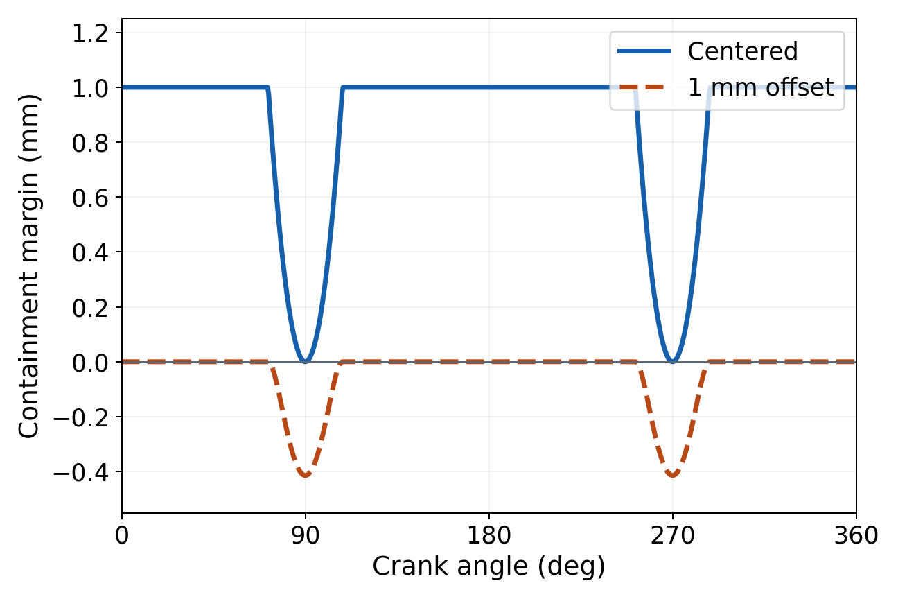
For the 46 mm slot at the upper extreme, those two offsets are each 1 mm. Their combined distance is √2 mm, exceeding the allowed 1 mm. The containment margin is 1 − √2 ≈ −0.414 mm. Even a height-only check that includes the pin radius would miss this curved-end violation.
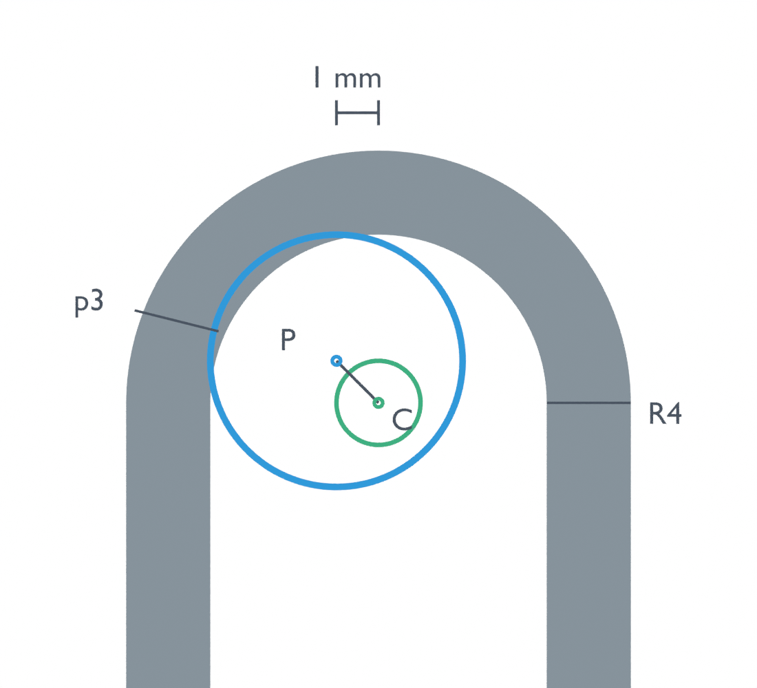
For a lateral offset δ, the full-turn requirement is:
L ≥ 2R + 2 max[0, r − √((R − p)² − δ²)],
provided |δ| ≤ R − p. Here r is the 20 mm crank radius. With δ = 1 mm, the bound rises to 48 mm. This is a containment limit: every fitting pose still has zero side clearance at that offset. More length cannot supply positive side clearance, and an offset greater than 1 mm cannot be accommodated by any length of this 8 mm opening with this pin.
The 46 mm slot with the 1 mm offset fails between approximately 71.805°–108.195° and 251.805°–288.195°. Those limits come from the geometry; they are not measured contact events.
What the Blender run checked
Codex executed the experiment through Blender MCP on October 5, 2026 in Blender 5.2.2 LTS. Each of the six cases recorded 721 poses from 0° through 360° in 0.5° steps. Counts use 720 unique angles, excluding the duplicate 360° endpoint. Pin and slot dimensions came from mesh vertices transformed into world coordinates, with meters converted to millimeters.
The centered 46 mm case had 718 clear samples and two tangent samples; its 1 mm offset case had 146 overlapping samples and 574 tangent samples. The centered 50 mm case was clear at all 720 unique angles. The 50 mm offset case contained the pin at all 720 angles, but every pose was tangent to a sidewall. This is why making the slot longer does not repair exhausted side clearance.
A separate supporting-line calculation reconstructed the capsule and circular pin from the recorded endpoints and radius. It agreed with the measured-coordinate containment margins within the experiment’s 0.0001 mm numerical tolerance. The complete native dimension and coordinate audit also passed that tolerance, with no classification mismatch. This is a software audit threshold, not a machining allowance.
The calculation treats the opening as an ideal capsule inferred from its defining mesh vertices. Rendered circular edges are polygon approximations, and the finite pin-rim samples are only a visual diagnostic. We did not run a mesh collision or rigid-body contact solver. An initial render also hid its front annotations because of camera clipping; the corrected close view preserves the same geometry and measurement file.
Decide where equality is acceptable
Start with total inner length, full width, pin radius, and the lateral offset your model prescribes. Check the distance to the cap-center segment throughout the pin’s vertical travel. Preserve a positive margin wherever you require separation from the boundary; equality means tangency.
The calculations prescribe the slot midline to follow the crank pin’s horizontal coordinate, with the stated constant offset. Because the slot is wider than the pin, that positioning is an assumption rather than a uniquely solved contact-driven motion. The experiment checks that prescribed planar geometry; it does not validate dynamics, friction, force, motor sizing or hardware operation. A design that needs positive clearance still needs an allowance chosen for its manufacturing and operating conditions; these nominal dimensions do not specify one.
Slot fit answers whether a finite disk stays in the chosen opening. For the separate question of output timing, our slider-crank and Scotch-yoke endpoint comparison examines how an ideal motion law changes time spent near a translating output’s endpoint.