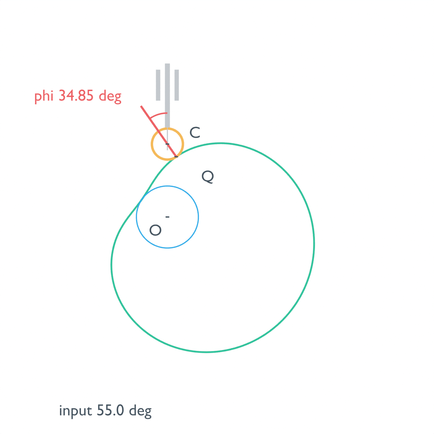
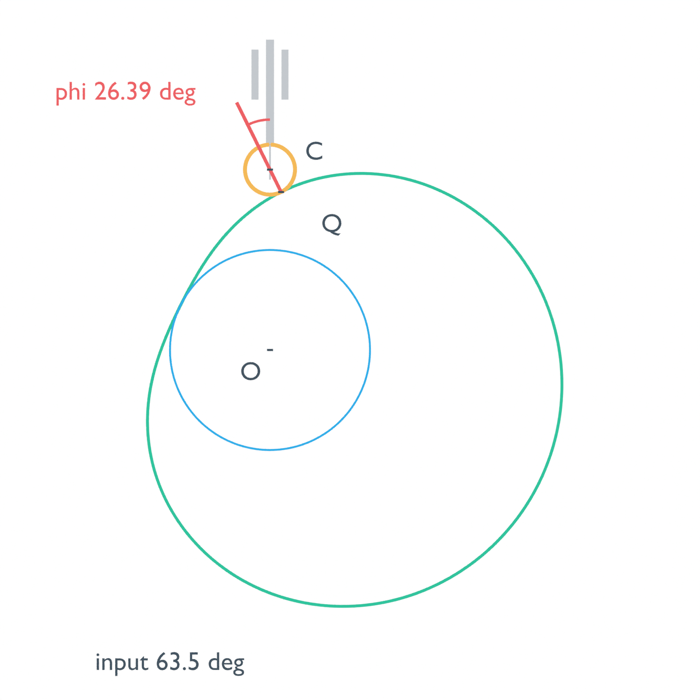
A smaller cam can preserve a roller follower’s stroke while making the contact normal more oblique to the follower’s travel. With the 40 mm harmonic lift and 5 mm roller radius examined here, a 10 mm cam base radius produces a peak pressure angle of 34.85°. Increasing the base radius to 20 mm reduces the peak to 26.39°. Against a declared 30° geometric target, the first misses the target and the second meets it.
This gives a useful sizing check before choosing a motor, guide or spring. Maximum lift alone does not reveal the worst contact angle. The roller-center path, its slope and the actual surface under the roller determine that angle.
Separate the cam surface from the roller-center path
The base circle is the smallest circle centered on the camshaft that touches the physical cam profile. Call its radius Rb. A roller of radius rr puts the lowest roller center one roller radius farther from the shaft:
R0 = Rb + rr.
Here rr is 5 mm. A 10 mm base radius therefore gives a 15 mm minimum roller-center radius. Substituting 10 mm for that center radius would describe the wrong geometry.
The roller center traces the pitch curve relative to the stationary cam. Its minimum radius R0 is the prime-circle radius. The physical cam surface is a different curve: it envelopes the roller circles along that path. CMU’s cam nomenclature and roller-follower construction explains the trace point, prime circle and envelope construction. These definitions support the model; the numerical comparisons below are our own geometry calculations and Blender readback.
“Pitch radius” needs a definition in a drawing. Here r means the current radial distance of the roller-center pitch point, which changes during lift. R0 remains constant. Neither should be confused with the pitch circle through the point of maximum pressure angle.
Calculate slope per radian before comparing angles
The example fixes an in-line translating roller follower with zero offset. It rises 40 mm over 180° and returns over the next 180°, with no dwell. Its harmonic lift law and derivative are
s(θ) = (h/2)(1 − cos θ) and s′(θ) = (h/2) sin θ, where h = 40 mm.
Use radians in these expressions. The derivative is in millimeters per radian; substituting a derivative per degree into the following relationship gives the wrong angle. The current center radius is r = Rb + rr + s.
Pressure angle φ is the acute angle between the common contact normal and the follower’s travel axis. For this radial, zero-offset geometry,
tan |φ| = |s′| / r.
A steeper lift curve increases the angle, while a larger center radius reduces it. Two cams with identical stroke can therefore impose different contact directions. Changing the lift schedule also changes the derivative, so a radius chosen for this harmonic cycle cannot simply be carried into another schedule. The separate slider-crank and Scotch-yoke timing comparison illustrates why equal stroke does not imply equal motion timing.
Find the worst pose instead of inspecting maximum lift
Let A = h/2 and B = Rb + rr + A. For this full-cycle harmonic law, the maximum pressure angle is arcsin(A/B). The first peak occurs at input angle arccos(A/B); the return has a corresponding second peak. At maximum lift, s′ is zero and the normal aligns with the travel axis. That apparently comfortable pose is not the worst angle condition.
The following comparison keeps the lift, roller radius and follower offset fixed. Peak angles and peak locations are analytical; the last column counts actual measured poses above the selected target in each unique 720-pose cycle.
| Cam base radius | Prime-circle radius | Analytical peak pressure angle | First peak input angle | Measured poses above 30° |
|---|---|---|---|---|
| 10 mm | 15 mm | 34.85° | 55.15° | 230/720 |
| 20 mm | 25 mm | 26.39° | 63.61° | 0/720 |
| 30 mm | 35 mm | 21.32° | 68.68° | 0/720 |
Thirty degrees is a declared target for this comparison, not a universal allowable angle for every cam. With a chosen target φtarget, the radius boundary follows from the same geometry:
Rb ≥ A / sin(φtarget) − rr − A.
For these inputs, the boundary is 15 mm. This value is derived, rather than a fourth simulated case. Exactly 15 mm gives a 30° peak with no angular reserve. The 20 mm case leaves 3.61° of reserve; 30 mm reduces the peak further while enlarging the cam. Select a target appropriate to the actual mechanism before using the equation as a sizing rule.
Place the contact point along the surface normal
In cam-fixed coordinates, the roller-center pitch point is P = (r sin θ, r cos θ). The physical surface point is Q = P − rr n, where n is the outward unit normal to that pitch curve.
Subtract the roller radius along the normal, rather than directly along every radial line. Those directions differ during motion. Drawing the lift onto the physical surface, or placing every contact point directly beneath the roller center, hides the very angle being checked.
In the moving world frame, the follower center C stays on the vertical travel axis. Define D = √(r² + s′²). The contact coordinates become
Qx = rr s′ / D and Qy = r − rr r / D.
The lateral contact coordinate is generally nonzero, even though the roller center has zero lateral offset. The line from Q to C supplies the measured contact normal.
The two native diagrams below show the whole measured cam outline in green, its base circle in blue and the roller in orange. O locates the shaft center; C and Q identify the roller center and surface contact. The red normal and arc show pressure angle against the vertical travel axis. Short gray stem and guide marks are schematic; their display length is not an experimental input. Both images use the same scale and separate sampled poses near their first angle peaks.
Check the surface construction before treating it as a usable cam
The roller radius matters beyond the pressure-angle calculation. If a convex pitch segment turns too tightly, its inward offset can develop a cusp. For these three profiles, minimum convex pitch-curvature radii are approximately 28.72, 40.31 and 51.23 mm, all larger than the 5 mm roller radius. The local offset regularity factor remains positive throughout each cycle.
The analytical outline is also simple and closed. A separate CPU boundary check compared roller centers with every segment of the 0.25° polygon representing that surface. The compact case showed a tiny negative segment clearance of about 0.000001322 mm from polygonal chord approximation. This is a numerical discretization effect, not simulated physical penetration. These checks support this particular construction; they do not certify manufacturing undercut, machining accuracy or a general roller-cam design.
On 5 October 2026, a scripted Blender 5.2.2 LTS experiment read actual transformed mesh coordinates at 721 poses for each of the three base radii, including the duplicate 360° endpoint: 2,163 records. Counting only the unique 720 poses produced the table’s 230/0/0 results. A separately written Cartesian normal reconstruction, using a sin-squared lift expression, checked the saved world coordinates without importing the construction helper. Its largest coordinate discrepancy was about 0.00001864 mm, and its largest pressure-angle discrepancy was 0.0001617°. The selected numerical tolerances were 0.0001 mm and 0.001°; they are readback tolerances, not manufacturing allowances.
The experiment prescribes cam rotation and follower-center placement. It does not solve contact forces, roller spin, spring retention, guide friction, acceleration loads or hardware performance. Use the result to choose and check geometry, then evaluate those physical requirements separately before building or operating a mechanism.