A stereo pair can cover a target with at least one camera while leaving much less of it visible to both. In our Blender fixture study, an 80 mm camera baseline gives either-camera coverage of all 900 sampled surface points, but only 522 points have two clear, in-frame sightlines. Moving the whole pair sideways restored the shared view; widening the lens alone did not. Check that shared view when choosing mounts for stereo correspondence.
These counts come from native Blender visibility tests checked against a separate world-coordinate calculation. They are not measured camera depth, a recognition result or a valid-pixel rate. The design question is practical: should you change the pair’s position, its field of view or its baseline to see a target behind a fixture?
One clear view does not supply the missing partner
For each surface point, make two tests from each camera origin. First, is the point inside the camera’s perspective frame and clipping range? Second, does the segment from the camera to that point intersect an opaque obstruction? A point belongs to the common set only when all four tests succeed.
The either-camera set is the union of the two visible sets. The common set is their intersection. Joining two camera previews in a dashboard can make the union look complete, even when neither image contains the counterpart needed to match some points in the other image.
Luxonis describes stereo disparity in terms of corresponding points in the left and right images. Its StereoDepth documentation separately explains how left-right checking rejects inconsistent disparity near occlusions. That is an algorithmic response to a visibility problem; it does not move the obstruction. This study models the preceding geometric condition and runs no StereoDepth pipeline. Luxonis stereo configuration, StereoDepth left-right checking.
The earlier workcell layout study separated gripper approach clearance from one camera’s view. Here the approach geometry stays out of the question: the required change is from one sightline to two sightlines for the same target point.
A fixture halfway to the target
The target is a 200 × 80 mm vertical plane, 600 mm in front of two parallel camera axes. An opaque rectangular fixture stands halfway along the viewing direction. It is 20 mm wide, 10 mm deep and 300 mm high. The cameras and the target center are 150 mm above the reference plane.
There are 100 horizontal sample columns and nine vertical rows, using the centers of equal-area cells. The resulting 900 points are surface samples, not image pixels or independent trials. Because this fixture blocks the full target height, all nine rows repeat the same horizontal visibility pattern.
On October 5, 2026, we ran this AI-operated virtual experiment in Blender 5.2.2 LTS. It recorded 4,500 point cases and cast 9,000 rays against the evaluated fixture mesh. Frame membership used each actual perspective camera’s projection and clipping limits. A separate script imported no Blender construction helper: it checked the saved world coordinates with pinhole equations and segment–box intersections. Projection error was 3.26 × 10⁻⁷ in normalized coordinates, and the largest world/hit-coordinate discrepancy was 5.97 × 10⁻⁸ m. These are numerical agreement checks, not camera accuracy or installation tolerances.
The comparison starts with a centered 20 mm baseline and 60° horizontal field of view. It then widens the baseline, widens the optics, moves the entire pair sideways, and finally narrows the optics at that new position. These are hypothetical matched, calibrated pinhole pairs. They are not selectable modes of one commercial camera, and moving a camera within a real stereo pair would require appropriate calibration.
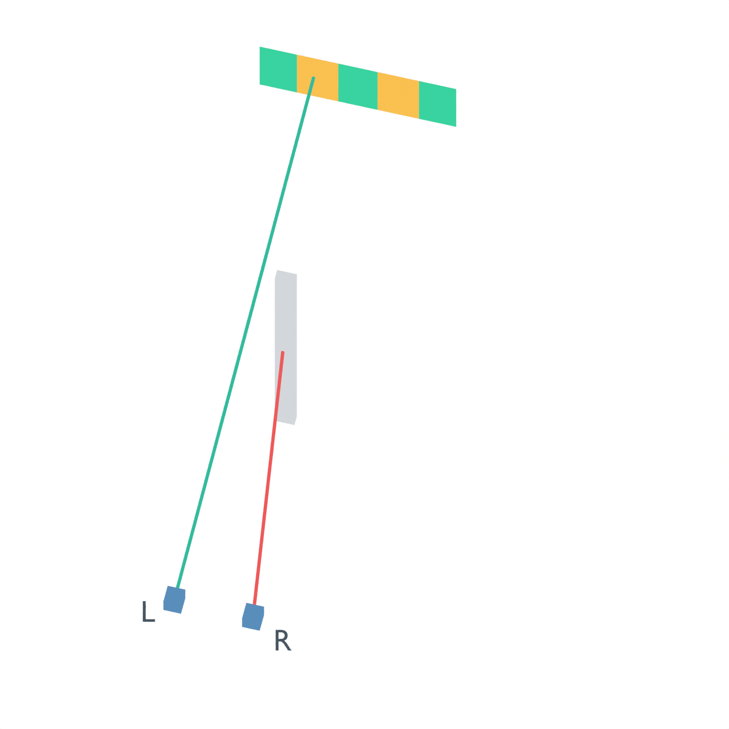
The gray solid is the actual modeled fixture. Blue cubes mark camera origins L and R; they do not represent camera-body dimensions. Green target cells have two eligible sightlines, orange cells have one, and gray cells would have neither. Each colored cell carries its center sample’s classification, rather than a claim about every point within that cell. These are overview diagrams, not rendered stereo photographs or depth images.
The wider baseline changes which points are hidden
The five native cases returned these counts. The independent pinhole-projection and fixture-intersection calculation agreed with every eligibility flag.
| Tested geometry | Left view | Right view | Either view | Both views |
|---|---|---|---|---|
| 20 mm baseline, centered, 60° | 720 | 720 | 810 | 630 |
| 80 mm baseline, centered, 60° | 711 | 711 | 900 | 522 |
| 80 mm baseline, centered, 90° | 711 | 711 | 900 | 522 |
| 80 mm baseline, shifted +200 mm, 60° | 900 | 900 | 900 | 900 |
| 80 mm baseline, shifted +200 mm, 50° | 900 | 630 | 900 | 630 |
All counts use the same 900 surface points. View here means in-frame and unobstructed. The fixture’s finite depth is included; replacing it with a zero-thickness screen changes some edge classifications.
At the wider centered baseline, the fixture hides a different band of target points from each camera. Every point is available to at least one camera, yet the common set drops from 630 to 522 points. Better union coverage therefore accompanies worse common coverage in this arrangement. It would be misleading to call that a stereo coverage improvement by looking only at a combined preview.
This is not a general finding that a smaller baseline is better. Baseline also affects depth geometry, and another fixture or working distance can produce another visibility pattern. The useful instruction is to evaluate both camera origins against the actual required surface, rather than treating baseline as a single monotonic quality control.
A wider lens cannot see through the fixture
Changing the centered pair from 60° to 90° expands both frames, but the target was already inside them. The obstructed camera-to-point segments do not move. The measured common count therefore remains 522.
Shifting the whole 80 mm pair by 200 mm in X does change those segments. At 60°, the tested placement clears the fixture from every sampled sightline and keeps the full target within both frames. Both cameras then see all 900 sampled points.
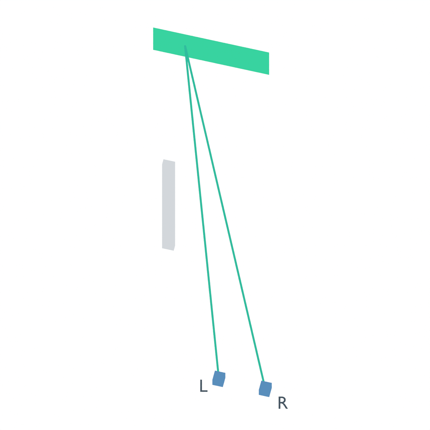
The apparent success has a narrow geometric margin. At the target plane, the shared 60° frame begins at approximately X = −106.410 mm; the target’s left edge is at −100 mm. Only about 6.410 mm separates that edge from the ideal common-frame boundary. The model includes no mounting error, distortion or crop, so this is not a justified real installation tolerance.
Narrowing the translated pair to 50° leaves the rays clear but excludes the target’s left portion from the right camera. The common count returns to 630. This failure is now framing, not fixture occlusion. Choosing an even wider lens or moving the pair again should follow that diagnosis, not a generic instruction to increase depth quality.
Use the result as a mounting check
Start with the surfaces your downstream task actually needs. A connector face, an edge used for grasp alignment and the whole bin floor are different target sets. Test the same points in each camera, retaining separate flags for out-of-frame and blocked. Report left, right, either and both counts; a single overall coverage percentage conceals the distinction this example exposes.
Then change one placement choice at a time. If a point is outside a frame, lens choice, crop or orientation may matter. If it is blocked, a wider frame alone cannot restore that ray. Consider the obstruction and camera positions. After the geometric check, validate the real camera’s calibration, texture, exposure, matching configuration and working range.
Our OAK zero-depth guide covers invalid outputs and configuration limits. Common geometric visibility is only a prerequisite for direct matching: a blank, reflective or poorly exposed surface can still fail after both cameras see it. This virtual study produced no depth map, measured no depth accuracy and tested no hardware.