A driver tip can line up with a screw while its shaft cannot pass through the enclosure lid. In our Blender geometry comparison, a 12 mm opening offset 4 mm from the drive axis admits a 2 mm bit but blocks the 6 mm shaft behind it. Enlarging the opening to 16 mm clears that shaft at a 30 mm drive depth. At a 50 mm depth, however, a wider collar reaches the lid and blocks the same tool again.
The useful design question is whether every tool section that enters the lid has room along the required insertion path. Neither a visible drive point nor a clear tip path answers that question by itself.
Keep the driver on the drive axis
The model fixes a vertical drive axis through the desired screw location. The driver stays on that axis and translates straight downward. The hole is offset from it; moving the hole changes the opening geometry without steering the tool away from the drive point.
The lid occupies Z = 0 to 8 mm. A drive point 30 mm below its underside has Z = −30 mm. The initial tip is at Z = 20 mm, above the lid. The model also includes enclosure side walls and a floor, with enough room for the specified tool in all five comparisons.
The illustrative tool has four finite sections measured upward from its tip: a 1 mm-radius bit from 0–20 mm, a 3 mm-radius shaft from 20–55 mm, a 5 mm-radius collar from 55–65 mm, and an 8 mm-radius handle from 65–100 mm. These are generic circular envelopes, rather than dimensions of a particular driver or fastener product.
NASA’s tool-access guidance distinguishes room for tool-head insertion and operation from clearance around the handle. That distinction is useful here; the spaceflight dimensions in that handbook are not inputs to this enclosure example.
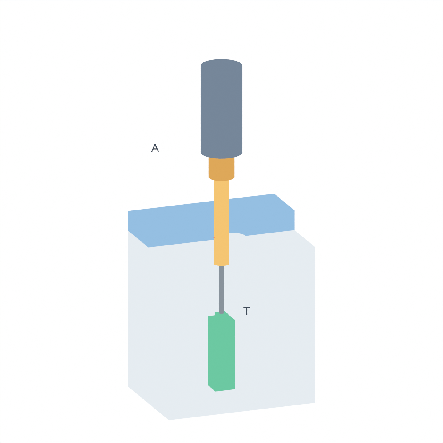
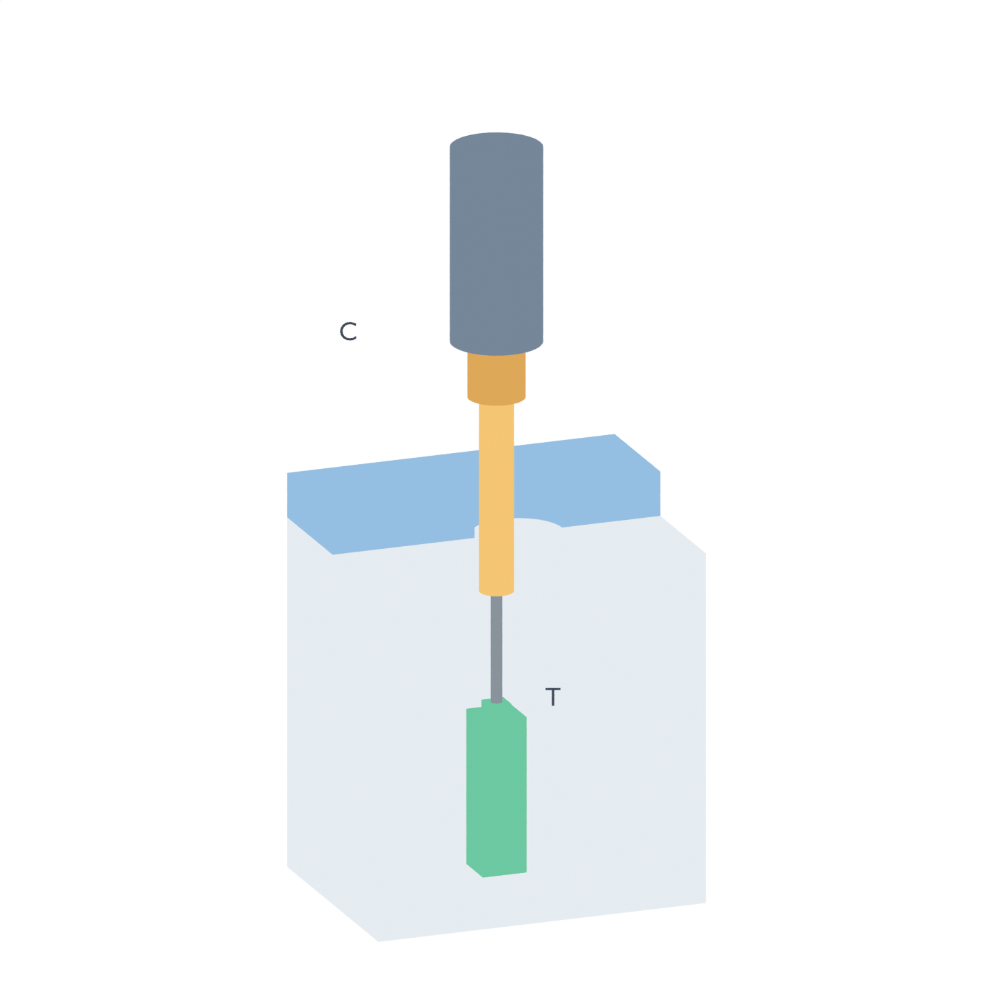
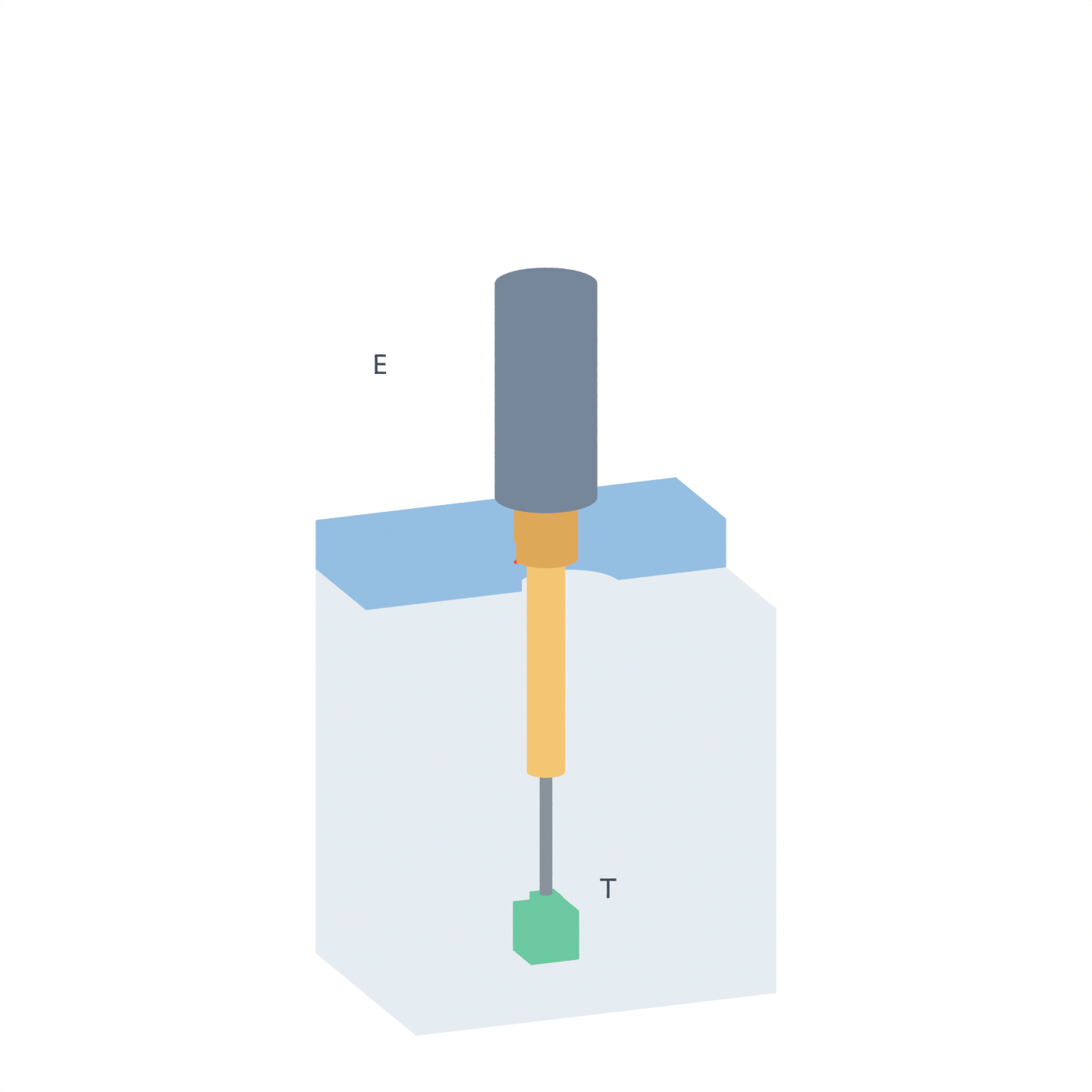
The blue lid and gray walls are sectioned to reveal the tool; their complete solids remain in the measured scenes. Orange sections are the shaft and collar, the dark lower section is the bit, and T marks the desired drive point on a green reference support. The images show prescribed geometry, including deliberately blocked poses, rather than a successful insertion.
Use the available radius, not just the hole diameter
Let H be the hole radius, e its offset from the driver axis, and r the radius of an active tool section. The farthest rim point from the hole center lies opposite the offset and is e+r away. Its signed radial margin is
c = H − e − r.
Positive c places the circular section strictly inside the opening. Zero means boundary contact. Negative c means the section extends beyond the available bore; it reports a geometric containment deficit rather than a physical deformation measurement.
For the 12 mm opening, H=6 mm and e=4 mm. Only 2 mm of tool radius remains available on the tight side. The bit radius is 1 mm, so it has 1 mm of margin. The shaft radius is 3 mm, giving a margin of −1 mm.
If a selected positive allowance is g, the corresponding opening requirement is
H ≥ e + r + g, with opening diameter D ≥ 2(e + r + g).
Using an illustrative 1 mm allowance with the same shaft and offset gives a 16 mm opening. The allowance is a design input here, not a printing tolerance recommendation.
Check which section actually reaches the lid
A large handle does not automatically require a handle-sized access hole. Its position matters. For a section spanning tool stations a to b, and a current tip height t, the section occupies
[t + a, t + b].
Its axial overlap with this lid is
Δ = min(t + b, 8) − max(t + a, 0).
When Δ<0, that section is outside the lid’s height interval. A negative radial margin then does not establish a lid collision. When both Δ>0 and c<0, the section and lid material have a positive solid intersection. An end cap merely touching a lid face remains a boundary-contact case.
At the 30 mm drive depth, the collar starts at Z = 25 mm and the handle at Z = 35 mm. Both remain above the lid throughout the downward insertion. At the 50 mm depth, the collar starts at Z = 5 mm and enters the lid’s thickness. Its 5 mm radius needs more opening room than the shaft did.
Compare two fixes and one deeper-drive failure
The five native comparisons keep the driver profile and drive axis unchanged:
| Hole diameter / offset (mm) | Drive depth (mm) | Limiting section | Radial margin (mm) | Result |
|---|---|---|---|---|
| 12 / 4 | 30 | Shaft | −1 | Intersects lid |
| 14 / 4 | 30 | Shaft | 0 | Boundary contact |
| 16 / 4 | 30 | Shaft | +1 | Separated |
| 12 / 2 | 30 | Shaft | +1 | Separated |
| 16 / 4 | 50 | Collar | −1 | Intersects lid |
Enlarging the hole and moving it closer to the drive axis both give the shaft 1 mm of ideal radial margin in the illustrated 30 mm-depth case. A 14 mm hole is the equality case: it removes the nominal solid intersection but supplies no positive radial reserve.
The collar begins reaching the lid when t+55=8, or t=-47 mm. Thus a drive depth below 47 mm keeps that collar above this lid. Moving the drive point farther down changes which radius must be checked, even though the opening and tool are unchanged.
Sweep insertion, then inspect the limiting part
On October 5, 2026, we ran this AI-operated virtual study in Blender 5.2.2 LTS. Each of five isolated scenes sampled 201 positions from the initial tip height to its drive point, yielding 1,005 native coordinate records. Both endpoints are distinct and counted. The original offset 12 mm opening has 72 sampled solid-intersection poses. Its shaft first touches the lid at 64% of the prescribed travel; the next sample, at 64.5%, has a positive intersection. The deeper-drive collar case has nine intersection poses near the end of its route. These percentages describe insertion distance, rather than elapsed time.
Native records preserve each section’s actual cap centers and farthest rim point, the hole axis and bore reference, and positive boundary-in-material witnesses in the blocked poses. A separate script imported no construction helper and checked disk support, finite height overlap and the witness coordinates. All classifications agreed; the largest coordinate discrepancy was about 0.00000657 mm against a 0.0001 mm numerical tolerance. Side-wall and floor margins stayed positive in this defined model. These checks reconstruct ideal circular envelopes from native points; polygon rendering approximates the circles and this is not a general arbitrary-mesh collision solver. The tolerance is a numerical audit setting, not a manufacturing allowance. Prescribing the tip at its destination in a blocked case diagnoses an invalid path; it does not demonstrate a completed insertion.
Before fixing an access-hole size, establish the drive axis, measure the full tool profile, and identify every section that passes through the lid during insertion. This model covers a straight coaxial circular envelope. Actual drive engagement, torque, hand space, tilted approaches and manufacturing variation require their own geometry or physical checks.
For a moving pin in a mechanism, the finite-pin Scotch-yoke slot study applies the related full-envelope check to a different opening shape and motion. Here the next design step is to size and locate the service opening using the largest tool section that actually enters this lid.