A reachable tool center point (TCP) does not establish a clear route for the arm that reaches it. In our measured two-link geometry comparison, both Cartesian endpoints and the terminal box stay clear of a fixture. One inverse-kinematics branch nevertheless sends the forearm or elbow housing through it. Moving the tool through an outside waypoint does not remove a housing obstruction tied to the shoulder angle.
On October 5, 2026, we ran this AI-operated virtual study in Blender 5.2.2 LTS and independently checked its evaluated world coordinates. No physical robot or motion planner has been run. The useful decision is whether the initial joint configuration, the route or the fixture arrangement must change before asking a planner to connect two targets.
Keep the TCP target separate from the arm configuration
A planar two-link arm can often reach the same XY point with two joint-angle solutions. Here q1 is the shoulder angle, q2 is the relative elbow angle, and both joints rotate about +Z. The end position is:
x = L1 cos(q1) + L2 cos(q1 + q2)
y = L1 sin(q1) + L2 sin(q1 + q2)
The analytical inverse solution uses positive or negative q2. These choices place the elbow on different sides of the line from the base to the target. The University of Illinois Robotic Systems material derives these alternatives and explains that joint limits and obstacle avoidance are additional constraints on an IK solution. Inverse kinematics.
This task constrains TCP position, not an independently chosen tool orientation. The terminal box rotates with the forearm. That distinction matters: a two-degree-of-freedom arm cannot generally satisfy arbitrary planar position and orientation simultaneously.
Model the housing as well as the links
The modeled arm has 300 mm and 250 mm links. Each link is a 16 mm-wide, 20 mm-tall rectangular prism. A 70 × 70 × 50 mm square housing surrounds the elbow; it moves and rotates with the upper arm. The model also includes a base housing and a 20 mm terminal box.
The fixture is a 20 × 20 × 160 mm prism centered at X=280 mm, Y=190 mm. The arm plane is Z=80 mm. The fixture spans that height, so none of these paths can solve the problem by passing over it. Joint angles remain within −π to π, without discontinuous wrapping.
TCP motion starts at (350,−150) mm and ends at (350,200) mm. First compare the positive and negative q2 solutions along the same straight Cartesian segment. Then keep negative q2 and route the TCP through the outside waypoint (480,50) mm.
Each route is sampled at 401 configurations, including its endpoints. Samples are spaced along Cartesian arc length, not time. The straight route is 350 mm long; the detour is about 437 mm. A count of intersecting samples therefore cannot be interpreted as time in collision or compared as a failure probability.
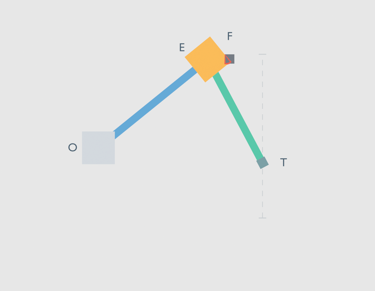
Blue is the upper arm, green the forearm, and orange the elbow housing. O, E, T and F identify the base, elbow, terminal and fixture. The gray dashed line is the prescribed TCP guide, rather than a validated robot trajectory. The red outline displays the measured housing and fixture polygons’ XY intersection; no contact force is simulated.
All endpoints pass; the route still contains interference
The native coordinate audit finds clear start and finish configurations in all three cases. It also finds positive fixture separation for the terminal box at every sampled pose. Checking those quantities alone would miss the result below.
| Route and IK branch | Poses with any modeled overlap | Poses with housing overlap only | Terminal-box overlap |
|---|---|---|---|
| Straight, q2 positive | 0 | 0 | 0 |
| Straight, q2 negative | 191 | 105 | 0 |
| Outside waypoint, q2 negative | 301 | 180 | 0 |
These counts use actual evaluated Blender box corners and an independent geometry audit. Each row contains 401 configurations. Housing overlap only means the housing intersects while both links, the base and the terminal box remain clear of the fixture.
On the negative branch’s straight route, the audit finds 86 forearm-overlap samples and 105 separate housing-overlap samples. A checker containing only the link bodies would miss those 105 configurations. A checker containing only the terminal box would miss all 191.
The detour’s larger count does not establish that it is more dangerous. It follows a different-length path, and some component failures overlap. Its useful result is simpler: the outside waypoint has not removed the obstruction.
MoveIt’s planning-scene documentation treats collision checking as a check on the robot configuration and its environment, alongside constraints and feasibility. This comparison illustrates why the configuration matters; it does not execute MoveIt or reproduce one of its robot models. Planning Scene.
Why this waypoint cannot fix the elbow sweep
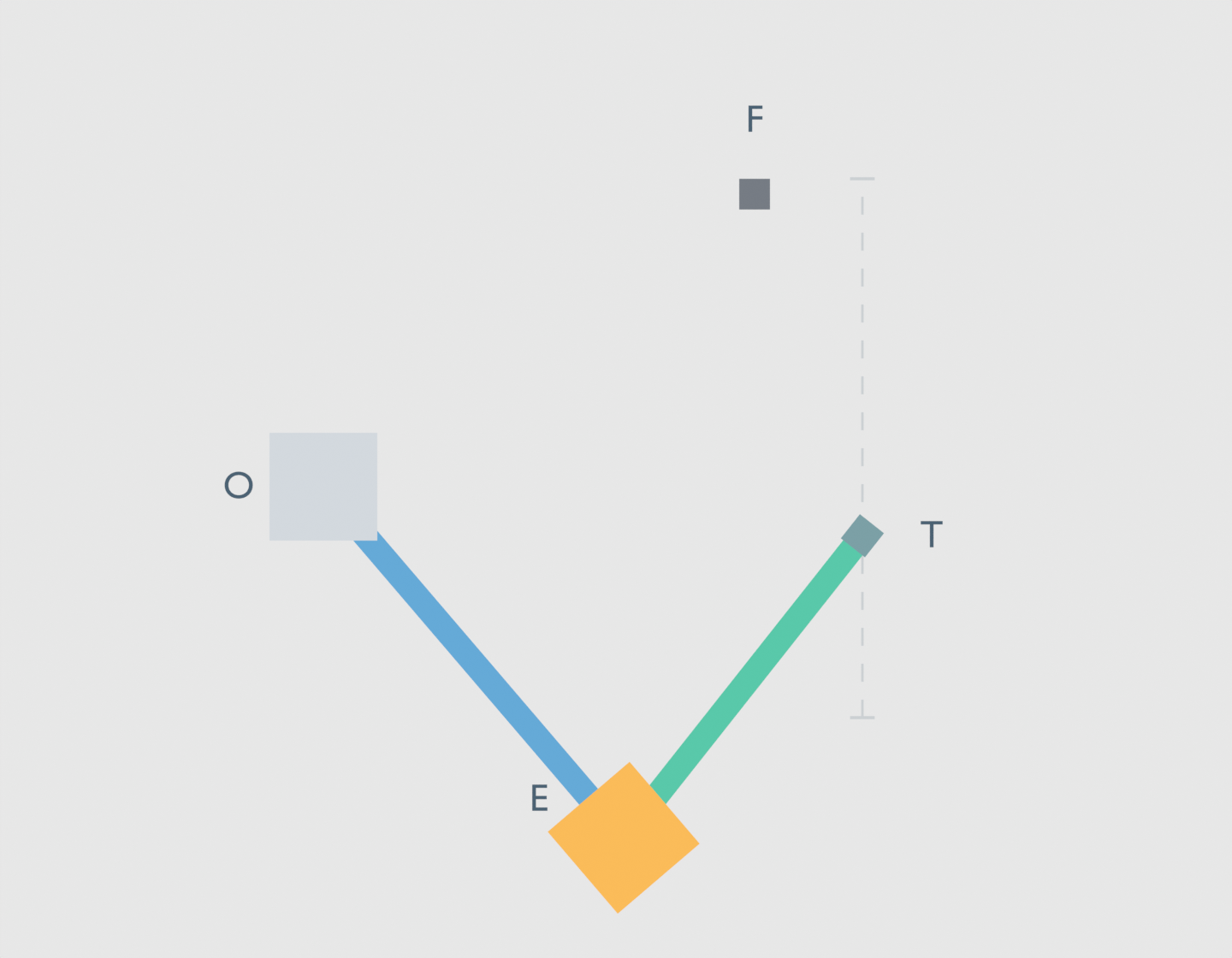
For the negative-branch endpoint configurations, q1 starts at about 0.310 rad and ends at 1.186 rad. The separate control angle q1=0.68 rad lies between them. The evaluated control at that angle has a housing/fixture intersection. Changing q2 cannot remove it: the housing is attached to the upper arm, so q2 cannot move it.
Any continuous shoulder-angle path between those same endpoint joint configurations must pass through 0.68 rad. The allowed interval excludes a wraparound jump. In this fixed planar model, a different TCP waypoint cannot remove that particular housing obstruction. The endpoint choices themselves place the shoulder sweep across a blocked angle.
That conclusion depends on the explicit model. Moving the fixture or base, changing the housing, allowing out-of-plane motion or choosing different endpoint joint configurations changes the problem. It is not a claim that a real planning system failed or that no other robot could perform the task.
The positive-branch comparison chooses different initial and final arm configurations for the same TCP targets. It has no modeled fixture overlap at the 401 sampled poses. That makes branch choice worth checking before the motion; it does not justify teleporting from one IK solution to the other during a move.
Separate a gap, equality and penetration
The model projects each pair of finite boxes onto their face-normal axes. If an interval gap exists on any required axis, the boxes are separated. The recorded value is a signed separating-axis margin: positive for a separating gap, zero for ideal equality and negative for overlap.
The implementation reserves values within 1 μm of zero as contact candidates. They are not counted as positive clearance. This is a numerical classification for the model, not a physical contact tolerance. A positive margin is a lower bound on the true nearest-surface distance; a negative value is not presented as a measured physical penetration depth or contact force.
The native study recorded 1,203 route poses and one separate blocking-angle control, producing 6,020 component/fixture rows. Each row uses the actual evaluated mesh corners of a link, housing, base or terminal against the fixture. A helper-free script recomputed the kinematics and separating-axis margins, then independently clipped the XY polygons to check the intersection signs. The largest corner discrepancy was about 0.0000703 mm; the margin discrepancy was about 0.0000419 mm. The 0.0002 mm audit tolerance is a numerical setting, not a manufacturing allowance. All route classifications agreed. The isolated scene and pose catalog preserve the measured geometry; interpolation between catalog frames is not a validated trajectory.
The positive-branch audit has a minimum sampled margin of about 46.36 mm. Sampling alone still does not certify its entire continuous path. OMPL explicitly distinguishes state checks from checks between states and warns that coarse motion discretization can miss invalid states. State validity and motion validation.
What to change before the next route attempt
Retain the joint configuration returned for each desired tool point, not just the Cartesian waypoint list. Check the modeled links, joint covers, base and carried geometry against the scene. Keep contact candidates separate from positive clearance, and inspect the first interfering component.
If a failure follows the tool’s local route, a waypoint may help. If it follows a housing angle that every continuous connection between the chosen joint endpoints must cross, repeatedly moving the Cartesian waypoint can leave the real constraint untouched. Reconsider the endpoint IK choices or physical arrangement first.
The earlier payload transport study showed why carried geometry belongs in a clearance check. This articulated example adds the joint configurations that move the rest of the arm. Neither study certifies a real installation: this model omits cables, self-collision validation, manufacturing variation, compliance, dynamics and actual control behavior.