In a ring-held planetary model, a carrier moving at +20 rpm can carry planets whose spin is −80 rpm relative to it but −60 rpm in the fixed frame. Assigning the relative value as a fixed-frame rotation produces the wrong motion even when the sun and carrier speeds look correct. The planet’s orbit and its spin need separate coordinates.
The difference is straightforward to handle in an animation hierarchy: move each planet center with the carrier, then apply planet rotation relative to that moving frame. This example uses a 40-tooth sun, 20-tooth planets and an 80-tooth ring, with positive rotation counterclockwise when viewed from +Z. The pitch radii are 20, 10 and 40 mm; planet centers orbit at 30 mm. These are synthetic dimensions, not a selected manufactured gearset.
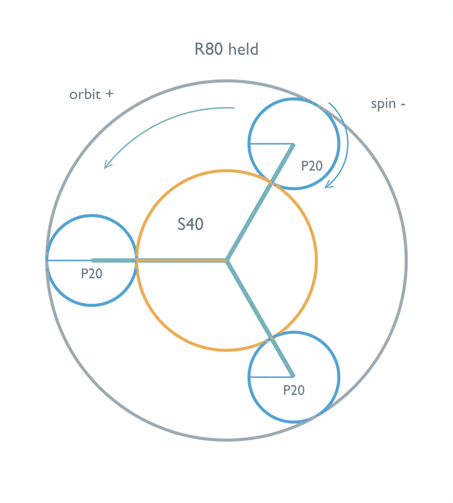
We prescribed five kinematic arrangements in an AI-operated Blender 5.2.2 LTS study on October 5, 2026, and independently checked evaluated markers, pitch-band meshes, body matrices and carrier arms. No physical gearbox was tested. The scene has no tooth contact, torque, backlash, friction or load-sharing model; the displayed bands are schematic geometry rather than contact surfaces.
Count the carrier rotation once
With the ring held and the sun driven at +60 rpm, the carrier moves at +20 rpm. The sun therefore turns at +40 rpm relative to the carrier. The external sun–planet pair reverses direction and doubles that relative speed because its tooth counts are 40 and 20: the planet’s carrier-relative spin is −80 rpm. Adding the carrier’s +20 rpm gives −60 rpm in the fixed frame.
For a planet nested under the rotating carrier, use planet_local_angle = planet_fixed_angle − carrier_angle. Its center inherits the carrier’s orbit; its local rotation then supplies the remaining orientation change. Using the fixed-frame planet angle unchanged for that child would count the carrier rotation twice.
The independent numerical control also checked the opposite mistake: treating −80 rpm as the planet’s fixed-frame spin. That creates a 20.944 mm/s ideal pitch-point velocity mismatch with these radii. The mismatch exposes incompatible prescribed motion; it is not measured tooth slip from a real gearbox.
KHK’s Gear Trains appendix explains pitch-point velocity matching and superposition when the support frame rotates. Applying that method to both ideal meshes gives Ns × (sun − carrier) + Nr × (ring − carrier) = 0. All member speeds must use the same unit and sign convention. Planet fixed-frame spin is carrier − (Ns/Np) × (sun − carrier).
Zero spin can still have an orbit
Prescribe sun +60 rpm and ring +30 rpm instead. The carrier becomes +40 rpm, while each planet has zero fixed-frame spin. Its orientation marker remains parallel to its initial fixed-frame direction even as its center travels around the sun. The actual native readback confirms that distinction.
In the same parent hierarchy, the planet needs −40 rpm locally to cancel the carrier’s +40 rpm. A zero local rotation would rotate its orientation with the carrier, which would be a different motion. The reference frame determines what a zero rotation setting means.
This arrangement is a deliberately specified second speed. It does not show that a physically free ring will settle at +30 rpm or that an unloaded planet will stop spinning. Inertia, loads, losses and initial conditions are absent from the prescribed model.
Supply the second speed before solving
Sun +60 rpm alone leaves the relation carrier rpm = 20 + (2/3 × ring rpm). Prescribing ring +15 rpm gives carrier +30 rpm and planet fixed-frame spin −30 rpm; prescribing ring +30 rpm gives the different arrangement above. An independent rational solver leaves one kinematic degree of freedom and returns undefined speeds for the sun-only input. Missing ring speed is not the same as a held ring.
Holding a member supplies that second constraint. In this example, holding the carrier and driving the sun at +60 rpm gives ring −30 rpm. Holding the sun and driving the ring at +60 rpm gives carrier +40 rpm. KHK’s Internal Gears technical information, printed page 208 distinguishes these configurations and lists the matching 40/20/80 ratios. Those nominal relationships neither specify loads nor endorse this code or scene.
The Python below reproduces the member speeds. None deliberately preserves the missing input. The three planets share the same ideal absolute spin in this example; their different center positions do not change that value.
Ns, Np, Nr = 40, 20, 80

def carrier(sun, ring):
    if sun is None or ring is None:
        return None
    return (Ns*sun + Nr*ring)/(Ns + Nr)

sun = 60.0
c = carrier(sun, 0.0)
planet = c - Ns/Np*(sun-c)
print(f"Ring held: carrier={c:.0f}, planet absolute={planet:.0f} rpm")
print(f"Carrier held: ring={-Ns/Nr*sun:.0f} rpm")
print(f"Sun held, ring=60: carrier={carrier(0.0, 60.0):.0f} rpm")
print("Sun only: carrier=", carrier(60.0, None))
for ring in (15.0, 30.0):
    c = carrier(sun, ring)
    p = c - Ns/Np*(sun-c)
    print(f"Prescribed ring={ring:.0f}: carrier={c:.0f}, planet absolute={p:.0f} rpm")
The native audit read 81 prescribed samples per arrangement over two seconds: 405 evaluated poses. It recovered multi-turn and reverse rotations from marker directions, checked every interval and both ideal pitch-point velocity equalities, and verified the finite pitch bands and carrier geometry. Agreement with the independent calculation supports the sampled kinematics; it does not demonstrate physical tooth engagement or validate arbitrary animation between samples.
When a modeled planet looks wrong, identify whether the rotation variable is local to the carrier or fixed in the scene, inspect the parent transform, and confirm the independently prescribed second member speed. For physical reducer selection, the planetary gear reducer guide covers backlash, load sharing and joint-level testing. For a separate pair’s actual tooth geometry, gear center distance and contact ratio address a different question from these pitch-circle rotations.