A 9.6 mm peg has 0.200 mm of radial clearance in a 10 mm bore when their axes coincide. Keep the peg tilted by 1°, however, and bore depth matters: an ideal 8 mm-deep opening retains about 0.060 mm of radial margin, while a 20 mm-deep opening reaches geometric contact at a tip-center depth of approximately 11.500 mm. Matching diameters at the entrance does not establish clearance farther down the bore.
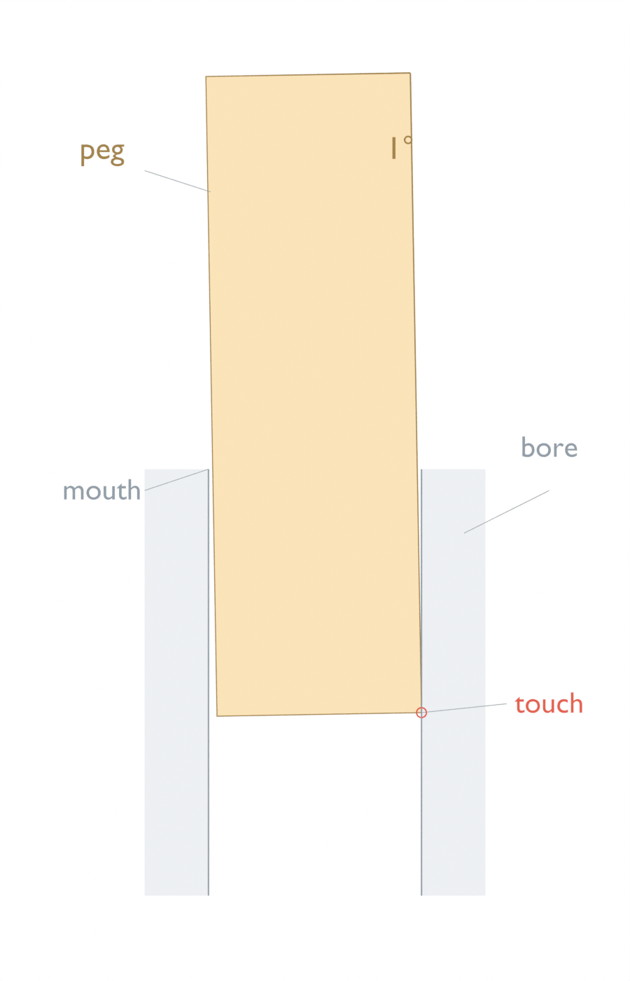
These results come from an AI-operated virtual geometric study in Blender 5.2.2 LTS on October 5, 2026, checked against an independent continuous calculation. No physical peg or bore was tested. They do not predict jamming, insertion force or the behavior of a chamfered, compliant or lubricated assembly. The peg here is 30 mm long, has flat ends perpendicular to its own axis, and advances along that fixed axis. The opening is a through-bore in a flat slab; there is no bottom to hit.
The first touch is behind the tip center
Start with the peg axis passing through the center of the bore entrance. As depth increases, the tilted axis moves sideways relative to the bore axis. In the 20 mm case, the first side-wall touch occurs at a tip-center depth of 11.500 mm. The contact point itself is at 11.416 mm: the tilted end disk places its widest right-hand edge slightly behind its center along the bore axis.
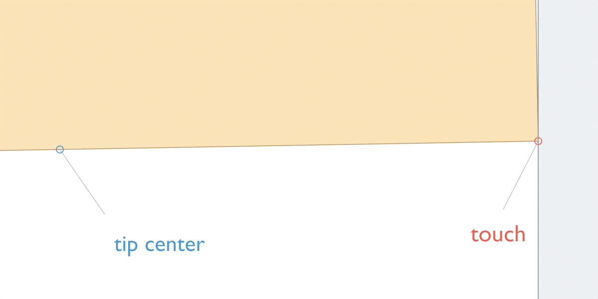
That distinction matters near contact. Treating the peg as an infinitely long shaft through the tip-center plane would include material beyond the actual flat end and predict contact too early. The calculation instead clips the finite peg to the actual bore depth and checks its two end caps as well as the entrance and exit planes. At first touch the radial margin is zero. Deeper prescribed poses cross the ideal wall; they are diagnostic configurations, not a path that a rigid peg can physically follow through solid material.
A short bore ends before the problem does
Now reduce only the bore depth to 8 mm. At a tip-center depth of 20 mm, much of the peg protrudes past the exit. That exposed portion is outside the slab, so it cannot collide with this bore wall. The part still inside has a minimum radial margin of 0.060 mm.
If the bore were incorrectly extended from 8 to 20 mm, the same finite peg at this position would have a radial margin of −0.148 mm. That would be a false interference report for the short bore. A correct check includes only the overlapping portions of both finite parts. Before the first part of the peg enters, and after its trailing end has completely left, there is no engagement; the margin is undefined, rather than a positive clearance.
Which center are you aligning?
For the 20 mm bore, the mouth-centered 1° axis produces a minimum radial margin over the full prescribed route of −0.150 mm. Moving that same axis sideways by −0.175 mm at the mouth places it through the bore center at half depth. The maximum lateral excursion is then shared between the two ends. The ideal minimum radial margin becomes 0.025 mm over the prescribed route.
This is a change in alignment target, not a hardware alignment recommendation. A 0.025 mm geometric margin says nothing about manufacturing variation, shaft straightness, surface condition, deflection or controller error, none of which is represented. Reducing tilt to 0° with the axis centered restores the original 0.200 mm margin regardless of which of these two bore depths is used.
The relevant design question is therefore where the finite engagement lies relative to the tilted axis. Entrance centering, halfway-depth centering and coaxial alignment are different poses. If a mechanism cannot hold the prescribed pose or accommodate real variation, this simple geometric calculation is insufficient to choose it.
For context, Van Wyk and colleagues’ NIST-hosted peg-in-hole study evaluates physical robotic insertion with compliant/force-controlled systems and measures completion time and success probability. Those are separate outcomes from a positive geometric margin; this calculation reproduces neither their experiment nor their performance results.
The peg-in-hole force-control guide covers approach, contact detection and bounded recovery for a physical assembly. Those control stages follow a geometric check; a positive margin alone supplies no force or completion criterion.
Reproduce these particular numbers
We read back 69 prescribed positions for each of four layouts: 276 evaluated poses. The finite 360-sided peg prism was checked against the bore slab, and an independent script recovered its pose and dimensions to evaluate the continuous circular cylinder. Empty overlap and boundary poses were checked separately. Frames index positions rather than time; numerical agreement does not establish manufacturing accuracy.
Distances below are millimeters. The bore occupies Z=0 to Z=H. The peg tilts toward positive X as Z increases; e is where its axis intersects the entrance. The three margin calculations apply when the finite peg spans the full slab. The first-touch expression is restricted to the mouth-centered, 20 mm-deep case described above, rather than a general insertion solver.
from math import cos, sin, tan, radians

r, R, length = 4.8, 5.0, 30.0
a = radians(1.0)
# Full section at both bore planes exists when the peg spans the slab.
for H, e in [(8.0, 0.0), (20.0, 0.0), (20.0, -10*tan(a))]:
    d = H + r*sin(a)  # tip disk has cleared the farthest section at Z=H
    assert d - length*cos(a) <= -r*sin(a)  # tail still clears Z=0
    radius_max = r/cos(a) + max(abs(e), abs(e + H*tan(a)))
    print(f"H={H:.3f}, e={e:.3f}: radial margin={R-radius_max:.3f} mm")

# This branch is specific to the mouth-centered, 20-mm-deep example.
d_touch = (R-r*cos(a))/tan(a)
z_touch = d_touch-r*sin(a)
assert 0 < z_touch < 20 and d_touch < length*cos(a)
print(f"First side-wall touch: tip-center d={d_touch:.3f}, contact Z={z_touch:.3f} mm")

# At d=20, the tip lies beyond an 8-mm slab: do not extend the bore to d.
actual_short = R-(r/cos(a)+8*tan(a))
# At d=20 in the incorrectly extended bore, this finite peg's extreme is
# on its tilted tip cap, not an infinite-cylinder cross-section at Z=20.
wrong_extended = R-(20*tan(a)+r*cos(a))
print(f"Short bore at d=20: correct={actual_short:.3f}, extended-bore error={wrong_extended:.3f} mm")
Here a negative margin means the ideal peg extends outside the circular opening within the slab. It is a radial containment measure, not a penetration-depth or force estimate. The finite calculation checks continuous cap and bore-plane boundaries; a few favorable cross-sections or a visibly clear render would not establish the same result.
For a layout check, specify the peg’s finite length and end shape, the actual bore depth, and where the tilted axis crosses the entrance. Check the shared region through entry, full engagement and exit. For a separate two-hole spacing problem, round and relieved locating pins explain how a second locator accommodates pitch error.