A flat plane can stop looking flat in a reconstructed point cloud even when every input distance is exact. One way to cause that error is to take a value defined as camera-axis depth Z, normalize the pixel ray, and multiply the two. That operation treats Z as the full camera-to-point distance instead.
Check the scalar and ray convention before tuning a reconstruction algorithm. A center pixel can pass this test while the off-axis geometry is wrong.
Take three points on a synthetic plane at Z=2 m. The on-axis point (0,0,2) is 2 m from the camera center. At (0.8,0,2), the distance is 2.154 m. At (0.8,0.6,2), it is 2.236 m. The axial depth is unchanged, but the diagonal camera-to-point segment gets longer.
This is the distinction between depth along the optical axis and Euclidean range from the camera center. It matters when a pixel and one scalar value are used to reconstruct a 3D point. A field called depth does not, by its name alone, establish which scalar or units a particular pipeline supplies.
The ray has two useful lengths
The OpenCV pinhole model projects camera coordinates by dividing X and Y by Z, then applying focal pixels and the principal point. Reverse that ideal projection for pixel (u,v) and the ray can be written as:
q = ((u−cx)/fx, (v−cy)/fy, 1)
This ray has an axial component of 1. Its total length is generally greater than 1. Multiplying it by axial depth reconstructs P = Z·q.
If the supplied number is instead Euclidean range rho, normalize the ray first: P = rho·q/||q||. The unit ray has total length 1, so multiplying by range gives the required camera-to-point distance. These two constructions agree when their input quantities are matched correctly.
For the off-axis point (0.8,0.6,2) m, substituting Z=2 m for range puts the reconstructed point only 2 m from the camera. Its axial depth becomes 1.789 m. The point has moved 236.068 mm toward the camera along the same ray. Using range as if it were axial depth makes the opposite mistake: this sample moves beyond the original plane, to axial depth 2.236 m, a 263.932 mm point shift.
An on-axis test alone hides the bug because the two scalars are equal there. A useful minimal check therefore includes both an on-axis point and an off-axis point whose true 3D coordinates are known in the synthetic test.
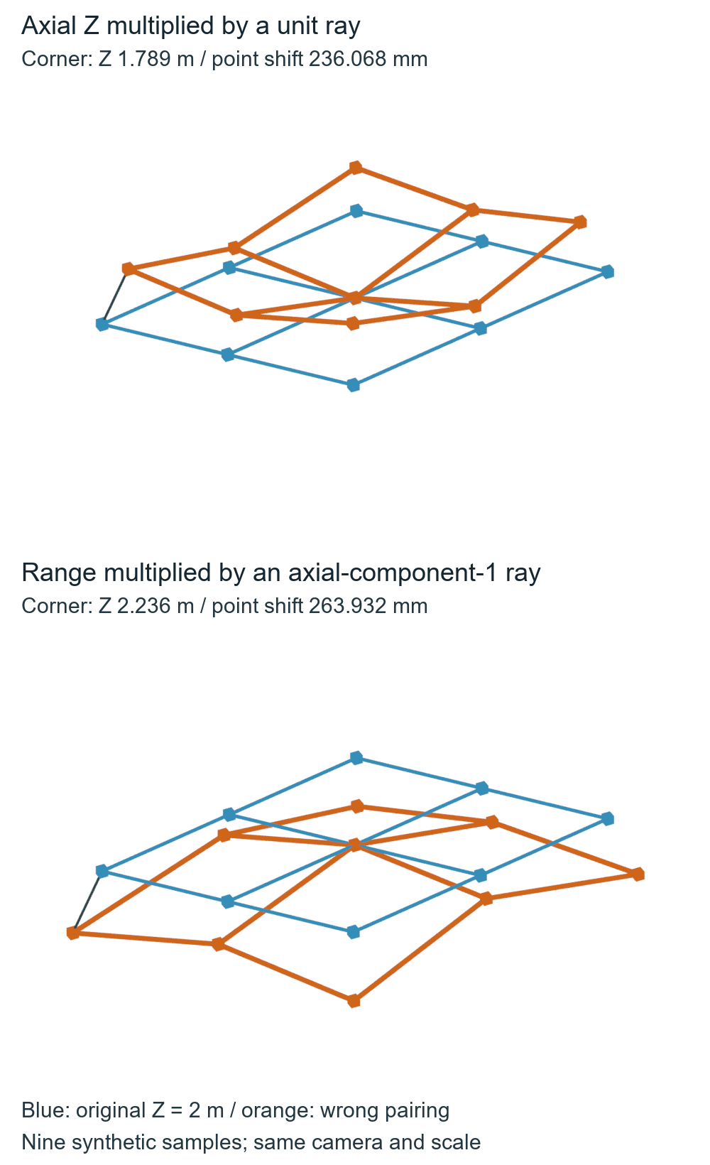
A plane of equal Z is not a surface of equal range
The finite target has nine samples at X=−0.8,0,0.8 m and Y=−0.6,0,0.6 m, all at Z=2 m. Correct axial-depth reconstruction leaves them on that plane. Using Z on unit rays instead places all nine at radius 2 m from the camera center; the off-axis samples are pulled in while the center stays fixed.
That result explains the apparent bending. It is a normalization error in the prescribed calculation, not a finding about a camera’s noise, lens distortion or a depth algorithm. The native diagram uses finite point/edge geometry; connecting samples does not turn it into an observed depth image or an exact continuous curved surface.
The executed standard-library code below reproduces three representative samples. All coordinates are in meters. Its synthetic 35 mm lens, 36 mm sensor width and 1200×800 image give focal length 1166.667 pixels in both directions and principal point (600,400). No distortion is modeled.
from math import sqrt, dist

fx = fy = 35 / 36 * 1200  # synthetic 35 mm lens, 36 mm width, 1200 pixels
cx, cy = 600, 400

def project(point):
    x, y, z = point
    if z <= 0:
        return None  # this example accepts only forward points
    return (fx*x/z + cx, fy*y/z + cy)

for point in [(0, 0, 2), (0.8, 0, 2), (0.8, 0.6, 2)]:
    z = point[2]
    range_m = sqrt(sum(v*v for v in point))
    u, v = project(point)
    ray = ((u-cx)/fx, (v-cy)/fy, 1)
    length = sqrt(sum(v*v for v in ray))
    unit_ray = tuple(v/length for v in ray)
    from_z = tuple(z*v for v in ray)
    from_range = tuple(range_m*v for v in unit_ray)
    wrong = tuple(z*v for v in unit_ray)
    assert dist(from_z, point) < 1e-12 and dist(from_range, point) < 1e-12
    print(f'{point}: Z={z:.3f} m, range={range_m:.3f} m; '
          f'Z on unit ray -> Z={wrong[2]:.3f} m, point error={dist(wrong, point):.3f} m')
assert project((0, 0, -2)) is None
assert project((1, 0, 0)) is None
Keep the camera axis separate from world Z
Axial depth is a projection onto the camera’s forward direction. Moving or rotating the camera changes the world coordinates of the plane without changing its camera-coordinate depth or range. Using world Z in the reconstruction would introduce another error.
This study recovers axis depth and ray length directly from evaluated camera and mesh coordinates. It does not read a sensor output or a rendered depth pass, so it cannot establish the meaning of a real device’s distance field.
The optical convention here is X right, Y down, Z forward. Blender camera-local coordinates use −Z forward and +Y up, so the geometry includes that conversion explicitly. The camera is also translated and rotated in the world so that world Z cannot accidentally reproduce the intended answer.
A point behind the camera can have positive Euclidean range while having negative axial depth. A point on the camera’s Z=0 plane can also have positive range, but the pinhole division is undefined. Those two controls retain a null forward reconstruction here. They are geometric states, not assertions about how a device encodes invalid pixels.
The AI-operated Blender 5.2.2 LTS study on October 5, 2026 retained a finite 1.6 × 1.2 m plane with nine vertices, four faces and twelve grid edges. An independent calculation checked the actual camera matrix and settings, optical landmark frame, every target and reconstruction vertex, finite rays and all eleven recorded point cases. Both correct pairings recovered the prescribed plane. At the off-axis corner, the actual readback gave 1.789 m axial depth when Z was used as range and 2.236 m when range was used as Z.
The native scene uses a synthetic 35 mm lens, horizontal 36 mm sensor and square pixels. OpenCV documentation resolved to 4.13.0; the separately inspected 4.x header is pinned to the examined source revision. No OpenCV solver, projection/depth-output API, image detector or calibration routine ran. Numerical comparisons used 3 micrometers for vertices, 5 micrometers for aggregate positions and 0.001 pixel for derived projections. A 1 micrometer axial guard retained the transformed zero-depth control as ineligible. These are floating-point audit guards, not sensor accuracy or physical validity specifications.
Before reconstructing points, establish the scalar’s documented meaning, units, intrinsics and coordinate frame. Then pair axial Z with a ray whose axial component is 1, or range with a unit ray. Test a known center and an off-axis point, and distinguish axial discrepancy from full 3D point displacement. For a stereo-derived Z value, the one-pixel depth-conditioning study explains a separate error source: how disparity perturbations affect the distance supplied to reconstruction. Correct normalization cannot fix a wrong correspondence or calibration.