A one-pixel correspondence change can move a stereo reconstruction by centimeters nearby and by hundreds of millimeters farther away. The reason is the reciprocal relation between disparity and depth. The same pixel change represents a larger share of a small distant disparity.
That statement does not assign an accuracy rating to a camera. A prescribed coordinate change is an input to a geometry calculation; it says nothing by itself about how often a matcher makes that change, or whether calibration, texture and timing are correct.
Luxonis’s official stereo-depth documentation gives the rectified relation Z = f B / d: focal length f in pixels, camera baseline B and depth Z in matching distance units, and disparity d in pixels. Here Z is depth along the camera axis, rather than Euclidean distance to an off-axis point. The calculations below use ideal parallel pinhole cameras and known point correspondence, rather than an OAK device or configuration preset.
Follow the same pixel change at two distances
Use a focal length of 800 pixels, a 60 mm baseline, and a 1280 × 720 image with its principal point at (640, 360). A point centered between the cameras at 1 m has nominal disparity 48 pixels. Hold its left-image coordinate fixed and move the corresponding right coordinate by −1 or +1 pixel. The disparities become 49 or 47 pixels, and the reconstructed depths become approximately 980 or 1,021 mm.
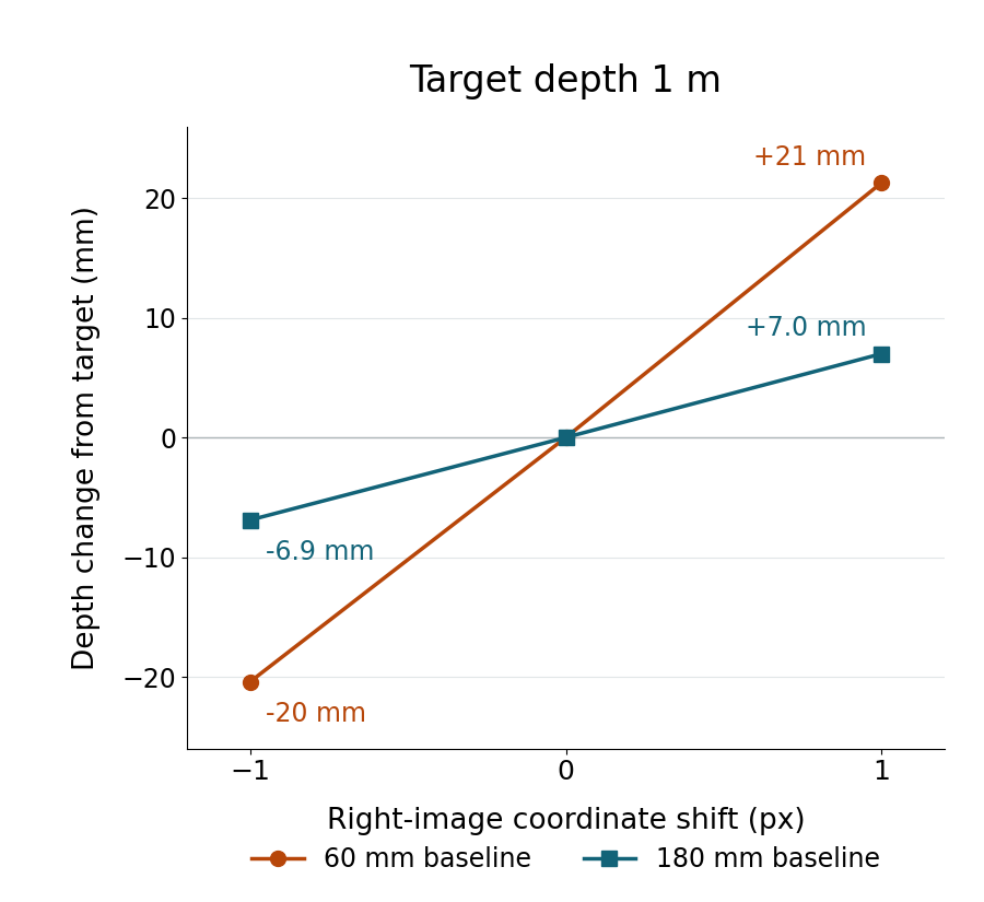
At 4 m, the same geometry has nominal disparity 12 pixels. The same right-coordinate changes give disparities 13 and 11, with depths approximately 3,692 and 4,364 mm. Those are changes of about −308 and +364 mm around the 4,000 mm target. The positive and negative depth changes differ because dividing by d−1 and d+1 is asymmetric.
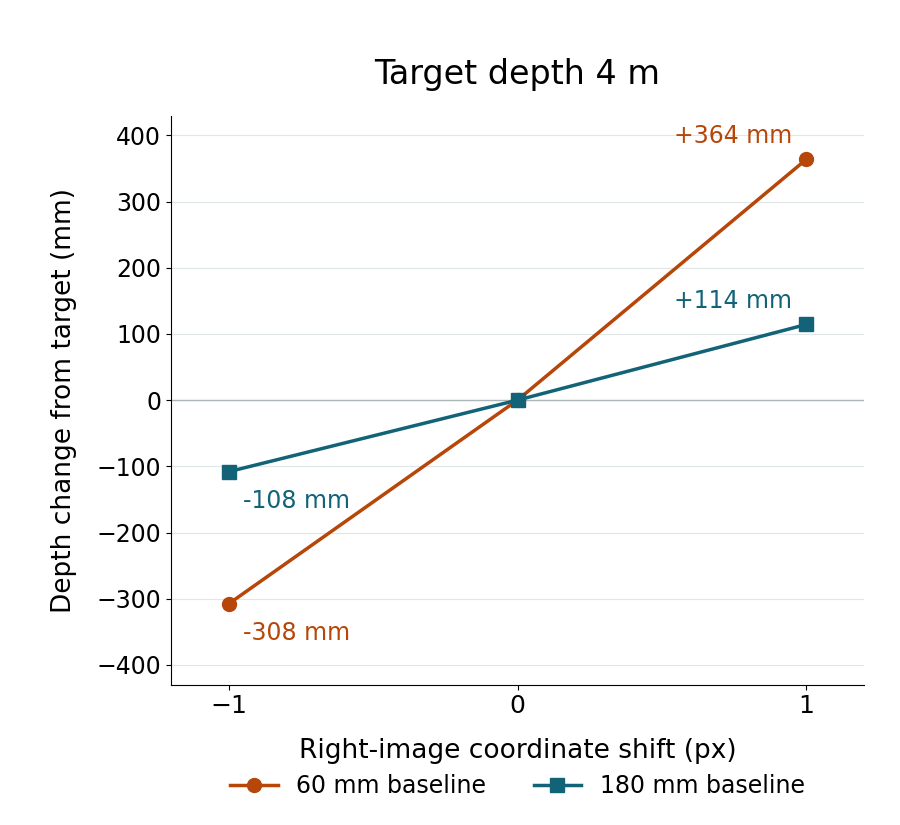
Widening the synthetic baseline to 180 mm, while keeping focal pixels and correspondence conditions unchanged, gives 36 pixels of nominal disparity at 4 m. The same one-pixel right-coordinate changes then produce approximately 3,892 and 4,114 mm. The narrower geometric interval explains the leverage of baseline; it does not prove that a wider real camera arrangement is always better. Shared visibility, occlusion, mounting constraints and matching quality were not modeled here.
An AI-operated Blender 5.2.2 LTS study on October 5, 2026 evaluated 21 finite camera, image-plane and ray conditions. An independent geometric audit checked the evaluated camera matrices, projections, finite target vertices, image-plane points, ray segments and reconstructed intersections. Twelve cases had eligible finite intersections; nine deliberately ineligible conditions retained a null accepted depth. The displayed rounded values agree with that actual readback. Software tolerances describe numerical consistency, not hardware accuracy.
The charts contain those evaluated intersection values, not photographs or rendered camera sensor frames. Connecting the three points helps compare the prescribed samples; it does not establish a matcher response between samples or a probability distribution.
Calculate a conditional interval before treating it as accuracy
If a disparity coordinate may change by a stated amount e, the reciprocal calculation gives f B / (d + e) and f B / (d − e), provided both denominators are positive and the intersections meet the chosen eligibility conditions. The interval is conditional on that assumption. Calling it a confidence interval would require separate evidence about the actual error distribution.
The familiar small-change approximation, magnitude of depth change ≈ Z² e / (f B), helps show why distance matters. It is a local approximation. When the change is a material fraction of disparity, calculate both reciprocal endpoints instead of reporting a symmetric ± value. At 4 m and a 60 mm baseline, one pixel is one twelfth of the nominal disparity, so the asymmetric endpoints are more informative.
The executed standard-library Python below reproduces the ideal reciprocal calculation. Its values are synthetic mathematics, rather than commands for a camera or measurements from a device.
focal_px = 800.0
for baseline_mm, target_mm in ((60, 1000), (60, 4000), (180, 4000)):
    true_disparity = focal_px * baseline_mm / target_mm
    depths = []
    # Hold the left coordinate exact; change only the right x coordinate.
    for right_pixel_change in (-1, 0, 1):
        disparity = true_disparity - right_pixel_change
        depth = focal_px * baseline_mm / disparity if disparity > 0 else None
        depths.append(round(depth, 3) if depth is not None else None)
    print(f"B={baseline_mm} mm, target={target_mm} mm, "
          f"d={true_disparity:.1f} px -> {depths} mm")

def accepted_depth(disparity):
    if disparity <= 0:
        return None
    depth = focal_px * 60 / disparity
    return depth if 50 <= depth <= 10000 else None

assert accepted_depth(0) is None
assert accepted_depth(-1) is None
assert accepted_depth(3) is None  # finite line intersection beyond our far clip
print("zero / negative / beyond-clip:", [accepted_depth(d) for d in (0, -1, 3)])
For an image pipeline, use the focal length in pixels for the exact image coordinate system being processed. Substituting the lens’s focal length in millimeters breaks the units. A resize changes focal pixels and the coordinate perturbation together. Cropping, rectification and shifted principal points also need to match the coordinates used for correspondence.
Some coordinate pairs have no eligible result. Equal horizontal coordinates give parallel rays in this model; a negative disparity gives an intersection behind the cameras. A positive disparity can still put the reconstructed point beyond the finite clip range. A vertical mismatch can make the rays fail to meet, while an out-of-image coordinate is rejected. Targets behind the cameras or outside the declared near/far bounds are separately ineligible. Null means no accepted reconstruction here; it is not a zero-distance object or a simulated device output.
The native geometry used a 50–10,000 mm clip range and a finite 2 mm target cube, with known correspondence to its center. Blender’s projection API documentation describes normalized image coordinates and depth along the view axis. The retained scene and audit test these explicit synthetic conditions. They do not test image matching, distortion correction, physical optics, synchronization or sensor noise.
Use this calculation to connect an assumed pixel difference to the distance change relevant to a task. Confirm the image intrinsics and coordinate conventions first, then keep a separate account of how the real correspondence was obtained. The existing shared-view camera-placement study covers whether both cameras can see a point around a fixture. If an OAK output is actually zero, the invalid-depth diagnostic guide addresses device validity, search ranges and filter behavior. Neither hardware issue is resolved by this geometric calculation, and no camera was physically tested here.