Three points can define a local coordinate frame only when they provide a baseline and a direction away from it. If the third point almost lies on the first two, a small displacement can swing the plane normal sharply. A long baseline alone does not prevent that problem.
Put marker A at (0,0,0) mm and B at (200,0,0) mm. Place C at (120,50,0) mm, then move only C upward by 0.1 mm. The triangle’s normal changes by about 0.115°. Keep A and B where they are, but put C only 0.1 mm away from their line, at (120,0.1,0) mm. The same upward displacement now changes the normal by 45°.
These are exact synthetic layouts and a prescribed displacement, not measurements of marker-tracking noise or robot accuracy. The contrast comes from the third point’s perpendicular distance to the baseline.
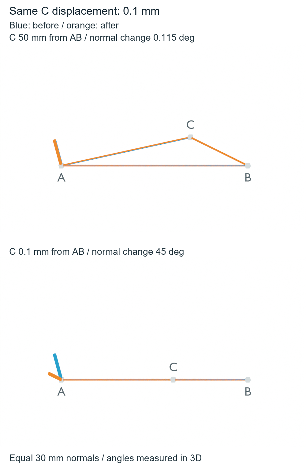
For a three-landmark orientation reference, check the third point’s transverse separation and preserve invalid cases explicitly. Normalizing a cross product does not remove the sensitivity of a narrow triangle.
The third point supplies the direction the baseline cannot
For this construction, A is the origin and the direction from A to B defines X. The ordered triangle A–B–C defines the positive plane normal Z. Finally, Y is Z crossed with X, completing a right-handed frame. Marker identity and ordering are part of that definition; changing their order can change the axes.
ROS REP-103 specifies right-handed coordinate systems. It does not prescribe this marker layout or make these geometric axes the physical forward, left and up directions of a particular robot.
The triangle normal comes from a cross product. Blender’s inspected triangle-normal source forms that cross product from point differences and normalizes it. Our calculation below uses its own standard-library implementation; the source function was not executed.
In the two layouts above, the nominal normal points along positive Z. After C moves, it is proportional to (0, −0.1, h) when h and the displacement are expressed in millimeters. For h=50 mm, the horizontal component is small relative to the vertical component. For h=0.1 mm, they have equal magnitudes, producing the 45° tilt.
The distance from A to C is about 120 mm in the narrow layout. That apparently substantial distance does not provide substantial transverse separation. Extending B farther along the same X line would also leave this particular normal change unchanged. The useful layout quantity here is C’s distance from the line, not just the distance between markers.
An undefined normal is different from a zero-degree change
If A, B and C lie exactly on one line, there is no unique plane normal. Multiple planes contain that same line. If A and B coincide, even the chosen X direction is undefined.
Move C out of an initially collinear line and the new triangle can have a defined normal. Its change relative to the original normal is still undefined, because there was no original normal to compare. Recording that result as 0° would incorrectly imply that a valid orientation stayed unchanged.
This small Python example uses meters and preserves those cases as None:
from math import sqrt, atan2, degrees

def cross(a, b):
    return (a[1]*b[2]-a[2]*b[1], a[2]*b[0]-a[0]*b[2], a[0]*b[1]-a[1]*b[0])

def length(v):
    return sqrt(sum(x*x for x in v))

def normal(A, B, C):
    AB = tuple(b-a for a, b in zip(A, B))
    AC = tuple(c-a for a, c in zip(A, C))
    n = cross(AB, AC)
    magnitude = length(n)
    return None if magnitude == 0 else tuple(x/magnitude for x in n)

A, B = (0, 0, 0), (.2, 0, 0)  # synthetic meters
for label, height in [('wide', .05), ('narrow', .0001), ('collinear', 0)]:
    before = normal(A, B, (.12, height, 0))
    after = normal(A, B, (.12, height, .0001))
    change = None
    if before is not None and after is not None:
        change = degrees(atan2(length(cross(before, after)),
                               sum(x*y for x, y in zip(before, after))))
    print(label, 'normal change:', None if change is None else round(change, 6), 'degrees')
assert normal(A, B, (.12, 0, 0)) is None
assert normal(A, A, (.12, .05, 0)) is None
Check the frame made from the points you actually have
The AI-operated Blender 5.2.2 LTS study on October 5, 2026 represented each marker by a 4 mm cube. It first recovered centers from all eight evaluated corners of each cube, constructed the frames from those centers, and read the completed geometry again. Eight condition records produced five defined frames; the three invalid frames have no invented axis glyphs. The scene contains eight marker meshes, eight triangle-edge meshes and five frame meshes.
An independent calculation recovered centers from opposite corner pairs and constructed axes by projecting the third point perpendicular to the baseline. It audited the finite vertices, topology, proper triads and actual frame glyphs. The measured wide and narrow normal changes were approximately 0.114579° and 44.999927°, consistent with the synthetic 0.115° and 45° explanation. Both undefined comparison controls remained null.
A common proper XYZ rotation of (15,−20,25)° and separate known display translations made the readback check world geometry rather than a convenient source plane. Only those translations were removed to overlay each pair in the diagram. The cubes are synthetic geometric markers, not a simulated camera’s detected observations.
That readback uses a selected 1 μm numerical guard on both baseline length and perpendicular separation to preserve the deliberately degenerate controls despite floating-point rounding. It is not a recommended marker tolerance or a claim that every smaller triangle is mathematically undefined. The reader example uses exact-zero rejection for its exact synthetic inputs; a noisy measurement pipeline needs a policy tied to its own uncertainty.
The audit used 4 μm for finite geometry, 1 μm for agreement between center calculations, 0.002° for producer/auditor angles and 0.1° for analytic/native agreement. These are numerical guards, not measured tracking accuracy. The inspected source revision is distinct from the installed Blender build; its triangle-normal routine was not executed. No camera detection, registration or calibration solver, ROS process, robot controller or hardware test was run.
Before treating three landmarks as an orientation reference, identify the ordered points, check that the baseline exists, and inspect the third point’s transverse separation. Then test the resulting axes against changes relevant to the intended data. The 0.115° and 45° results explain this one geometric sensitivity; they do not set a universal minimum spacing or establish the accuracy of a real localization system.
The hand–eye translation study shows a related geometry limit: independent motion directions can constrain a rotation, while pure translations leave the camera offset undetermined. This marker study instead asks how three known points define a frame, and how that frame reacts when one point moves.