If a Nav2 route drawing shows an intersection but the intended turn has no path, check the node IDs and directed edge endpoints before tuning the planner. In the GeoJSON loader examined here, Point features create nodes, and each edge’s startid and endid determine its connection. Two lines crossing on the map do not create a junction automatically. Two nodes at the same coordinates also remain separate if they have different identities.
The practical check is to trace an outgoing chain of IDs from your start to your destination. A line that passes over another line, a dot drawn at the crossing, or matching coordinate values cannot substitute for that chain. Direction matters too: an edge A→B does not, by itself, add the reverse edge B→A.
This article examines Nav2 tag 1.5.2, commit 7b9be248a652224a19305469fd5e854d50512341, checked on October 6, 2026. The claims concern graph construction in the pinned GeoJSON loader. They do not establish which version is installed on your system, compatibility with every editor export, or how every other Nav2 component uses geometry.
Follow the endpoint IDs through the loader
The loader first classifies features by geometry type. A Point becomes a node candidate. A LineString or MultiLineString becomes an edge candidate. That distinction matters, but it does not make the line’s shape the source of adjacency.
For each Point, node construction reads properties.id, records the ID-to-node mapping and assigns the Point’s coordinates. For each edge, edge construction reads its own id, startid and endid. It resolves the two node IDs and adds an edge to the start node’s outgoing neighbors.
The edge’s own ID identifies the edge record. Its start and end IDs refer to node records. Confusing those roles can leave a visually sensible export connected to the wrong nodes—or referencing nodes that do not exist.
At this loader boundary, the LineString coordinate array is not read to decide which nodes are adjacent. The node coordinates come from the Point features, and connectivity comes from the endpoint references. That does not mean you should remove line coordinates or let linework disagree with its nodes. It means that fixing the drawing alone does not establish that its endpoint references were fixed too.
The same crossing can describe three different graphs
Consider four node positions in one illustrative map frame, measured in metres: left L at (−0.7, 0), right R at (0.7, 0), bottom B at (0, −0.7) and top T at (0, 0.7). Give them IDs 0, 1, 2 and 3 respectively. Horizontal and vertical lines between those positions cross at the origin.
These are the authored inputs for the geometry comparison below. The endpoint pairs are deliberate graph choices; they are not connections discovered from the drawing.
| Graph construction | Center identity | Directed endpoint pairs |
|---|---|---|
| Crossing without a junction | No center node | 0→1 and 2→3 |
| Shared junction | One node, ID 4, at (0, 0) | 0→4, 4→1, 2→4 and 4→3 |
| Same position, distinct identities | ID 4 and ID 5 both at (0, 0) | 0→4, 4→1, 2→5 and 5→3 |
In the first construction, left-to-right and bottom-to-top linework cross, but the endpoint pairs provide no transfer between them. In the second, you can read the chain 0→4→3 directly: both the horizontal and vertical branches refer to the same junction identity. In the third, the horizontal branch uses ID 4 while the vertical branch uses ID 5. Equal coordinates do not supply an edge from 4 to 5 or combine their outgoing neighbors.
This distinction is easy to miss when an editor renders both center points as one dot. Inspect the identities and incident edge records, not only the symbol at the intersection. All node IDs in these examples are unique within their graph. They do not test duplicate-ID handling, which is a different malformed-input question.
For the shared-junction case, the two edge-property records needed for the particular L-to-T chain look like this:
[
  {"id": 9, "startid": 0, "endid": 4},
  {"id": 12, "startid": 4, "endid": 3}
]
This is an identity-reading excerpt, not a complete loadable GeoJSON file. Nodes 0, 4 and 3 must exist as Point features; full edge features also need their geometry and surrounding feature structure. The excerpt’s useful question is whether the first edge’s destination is the same node identity as the next edge’s source.
A shared node still does not make travel bidirectional
The examined Node::addEdge method appends one directional edge to the current node’s neighbors. Its start is that node and its end is the supplied destination. It does not append a reciprocal edge to the destination.
The pinned sample graph makes this explicit: one record represents 0→1 and a separate record represents 1→0. The reverse record has its own edge ID. Drawing one segment over another in the opposite direction does not tell you whether both records survived export; check the endpoint pairs.
In the shared-junction example, L-to-T has the authored chain 0→4→3. For the reverse journey, the required chain would be 3→4→0, and those pairs are absent from the listed input. Add reverse directions only where they are intended by the route design, and inspect the complete requested chain rather than reversing a single edge and assuming the whole journey is available.
The repository’s simple-graph test source likewise expects one outgoing neighbor at the source and none at the destination for its single-edge example. We read those assertions; we did not compile or run the repository tests. They support the source interpretation, not a claimed test pass in our environment.
Check the export before changing planner settings
Work from the actual file the Route Server will load, then trace one failing direction. The following checks locate different kinds of mistakes:
- Find the node identities. List the Point feature IDs around the apparent intersection. Determine whether the center is missing, shared, or represented by distinct co-located IDs.
- Resolve each edge’s endpoints. Check that every relevant
startidandendidnames an existing node. Compare the referenced Point coordinates with the intended drawn endpoints. - Trace outgoing pairs. Starting at the requested node, follow the available directed pairs. Record where the chain stops; do not jump to another ID merely because its coordinates match.
- Check the requested reverse direction separately. Inspect the reverse records and their edge IDs. A valid forward chain does not establish a valid return chain.
- Then inspect other route conditions. A connected authored graph only settles this connectivity question. Costs, operations, start/goal handling and other runtime conditions can still affect route availability.
The current Rolling graph-generation guide describes a QGIS workflow that assigns edge direction and generates start/end node IDs. Those authoring steps matter because the exported identity references must agree with the intended drawing. This is a separate living workflow document, not a claim that its current UI, SQL or export behavior is identical to the examined 1.5.2 loader. We did not execute QGIS, SQL or the editor workflow.
Do not assume a malformed export will always be rejected with the same error. In the pinned edge-loading code, an absent referenced start or end node throws NoValidGraph. The inspected test source also expects a JSON exception for a missing node ID. These examples are not a complete schema-validation guarantee, and a file containing all referenced IDs can still describe the wrong connections.
What the measured crossing comparison shows
We constructed all three cases in one actual Blender 5.2.2 LTS run on October 6, 2026. The scene contained 25 separate closed prism meshes: 15 node markers and 10 edge markers, with 200 vertices in total. An independent audit recovered node centers and edge centerline endpoints from the evaluated vertices. It inverted the common rigid 3D transform and the per-case display offsets to express each case in its own map frame.
The figure therefore plots measured marker geometry. Its arrows follow the separately authored endpoint IDs. The yes/no answers come from an executed standalone breadth-first search over those directed IDs, not from Nav2’s C++ loader, Route Server or planner. No geometric intersection was allowed to insert an extra adjacency into that model.
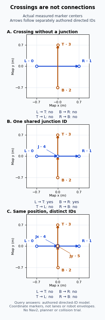
| Case | Measured geometry, lengths rounded | L→T / B→R in authored model | T→L / R→B in authored model |
|---|---|---|---|
| A: no junction, 4 nodes | Two 1.4 m edges cross in their interiors; no center node | No / No | No / No |
| B: shared ID 4, 5 nodes | Four 0.7 m edges meet at the shared node | Yes / Yes | No / No |
| C: distinct IDs 4 and 5, 6 nodes | Four 0.7 m edges; the two center nodes have measured separation 0 m | No / No | No / No |
In case B, the returned node paths were L→T: 0→4→3 and B→R: 2→4→1. In case C, the two center markers had identical recovered coordinates, yet the graph model still had no transfer between IDs 4 and 5. The shared-node case therefore changes the identity chain without changing the intended crossing layout. Its missing reverse routes also show why a shared junction alone is insufficient for a return journey.
As a numerical consistency check on these digital markers, the largest measured endpoint-to-referenced-node discrepancy was approximately 0.00031 mm in A, 0.00025 mm in B and 0.00025 mm in C. Each was below the fixed 0.008 mm allowance for derived distances. Those small residuals describe floating-point mesh and coordinate reconstruction in this experiment. They are not measurements of robot accuracy, positioning repeatability or a Nav2 acceptance tolerance.
The experiment establishes a bounded geometric illustration and the behavior of the authored directed graph model. The separate source review explains why the same identity distinction matters at the inspected loader boundary. We did not run Nav2, ROS, Route Server, a planner or a controller. No sensors, traffic, collision, physical robot or safety behavior was tested; a graph path here says nothing about whether a robot can traverse the pictured turn.
Separate connectivity from association and traffic coordination
First establish that the intended identities have an outgoing path. If the graph is correct but a reported robot pose is associated with the wrong lane or waypoint, that is a different problem. The RMF graph-merge tolerance experiment examines pose-to-existing-graph association; it does not make an unconnected authored graph connected, and its RMF parameters are not Nav2 loader settings.
Likewise, an available graph path does not establish that a door, lift or shared corridor can be used at that moment. The Open-RMF architecture guide covers fleet and facility coordination. The AMR traffic deadlock guide covers ownership and circular waits. Those issues require state beyond endpoint IDs and are not tested by this comparison.
For an apparent crossing that refuses a turn, the immediate diagnostic stays narrow: identify the center node, read the edges that enter and leave that same ID, and trace the required direction. A correct-looking intersection is evidence about the drawing; the endpoint records establish the graph connection examined here.