When a Nav2 docking target looks wrong, first identify which pose you are looking at. The database holds the configured dock location. The selected dock plugin derives a staging pose from it. The docking server then creates a separate local estimate that the plugin can refine, and the approach loop derives another target for the controller. These poses have different roles; changing the local estimate does not mean the database entry or action goal was rewritten.
For debugging, record the dock instance, loaded plugin, frame and timestamp alongside each pose. A staging offset, a perception correction and a controller projection can all move a displayed target for different reasons. Comparing their x and y values without those labels can make correct behavior look like a calibration error.
This article examines the docking code included in Nav2 tag 1.5.2, commit 7b9be248a652224a19305469fd5e854d50512341, checked on October 6, 2026. Implementation statements refer to that exact version. The rolling docking tutorial and rolling server configuration guide provide context, but they are living documents. Neither establishes which docking implementation is installed on a particular robot, and the examined Nav2 copy is not a claim about every release of a separate docking repository.
The instance selects a record; its type selects a plugin
A dock instance is a named location, such as bay_a. Its type identifies the configured plugin that supplies docking behavior. Several instances can use the same loaded type, so two docks can share the same staging logic while having different stored positions and orientations.
The examined database parsers require a type and a three-element pose array. They interpret the pose as [x, y, yaw], constructing a planar orientation from yaw. The frame defaults to map when omitted. An optional id is a separate field from the instance name.
| Item | Role in the examined path | What to check |
|---|---|---|
Instance name, such as bay_a |
Key used to look up a stored dock | Whether the action’s dock_id selects the intended entry |
type |
Key used to find a loaded dock plugin | Whether that type is loaded, and which implementation and parameters it uses |
frame |
Reference frame of the stored pose | Whether later transformations use that frame correctly |
pose: [x, y, yaw] |
Stored location and planar orientation | Metres for x/y and radians for yaw; dock orientation matters to offsets |
Optional id |
Additional value passed to pose refinement | Whether the chosen plugin uses it; it is not the database lookup key |
In DockDatabase::findDock, lookup finds the instance first, then finds its type’s plugin and attaches that plugin to the returned dock record. An existing record with an unavailable type therefore does not become usable merely because its coordinates are valid.
There is also a route that does not look up an instance. The tutorial describes configuring database instances, but the examined server branches on use_dock_id. With that flag false, generateGoalDock constructs a temporary dock from the explicit action pose, frame and dock type. A suitable plugin still has to be available. This source path is why the tutorial’s instance-oriented instructions should not be treated as a universal requirement that every action must name a database entry.
Staging position follows dock yaw, even when heading differs
The database does not store a universal staging formula. Dock::getStagingPose delegates the stored pose and frame to the attached plugin. The ChargingDock interface defines that responsibility; a particular plugin decides how to fulfill it.
For the examined SimpleChargingDock::getStagingPose, let the stored dock pose be (x, y, θ), the staging x offset be d, and the staging yaw offset be α. The planar calculation is:
staging_x   = x + d cos(θ)
staging_y   = y + d sin(θ)
staging_yaw = θ + α
The displacement follows the stored dock yaw θ. The yaw offset changes the staging heading separately; the code does not first add α and then use that new heading to translate the position. A negative x offset moves opposite the dock’s local x direction, which will generally affect both global x and global y. Subtracting the offset only from global x is a different operation.
The examined SimpleChargingDock defaults are −0.7 m for staging_x_offset and 0 rad for staging_yaw_offset. These are defaults for this implementation, not a universal stand-off requirement for every dock. Another loaded type—or another configuration of the same implementation—can produce a different staging pose from the same stored coordinates.
Computing staging also does not guarantee that the robot navigates there. The reviewed server path can bypass navigation when requested or when the robot is within the configured prestaging tolerance. Separate the derived pose from the decision to navigate to it.
Refinement changes the local estimate used for approach
After staging, the server calls getDockPoseStamped. This copies the dock’s pose and frame into a new stamped message. The server transforms that local message into its configured fixed frame, then passes it to the initial refinement loop. The initial estimate is a copy of the dock location, not a copy of the staging pose.
getRefinedPose receives the local message by mutable reference. In the reviewed initial and approach callers, that reference is the working dock estimate. The subsequent approach loop continues using it. These callers do not assign the refined value back into the database pose or overwrite the action goal. That is a statement about the inspected data flow, not a guarantee that every custom plugin is free of other side effects.
The word refined does not guarantee that a sensor changed anything. In SimpleChargingDock’s refinement function, the external-detection switch creates two distinct paths:
- With external detection disabled, the function publishes and internally stores the incoming local pose, then returns true. It leaves the caller’s pose unchanged.
- With external detection enabled, it first requires a received detection and checks its age. It transforms the detected pose into the estimate’s frame when needed, filters it, applies configured orientation and translation offsets, and assigns the resulting pose to the caller’s reference. Missing, stale or unavailable-to-transform input can return false.
The enabled path’s translational offsets use the corrected dock yaw after the orientation adjustment; roll and pitch are removed for the resulting planar orientation, and the dock position’s z is set to zero. A marker detector’s raw pose, its filtered pose and the resulting dock pose can therefore differ for legitimate configured reasons. Log those stages before deciding that the database needs to move.
The interface also passes the dock’s additional id into refinement. The examined SimpleChargingDock function does not use that argument, while a different plugin can. Do not assume that changing an optional id changes lookup or perception behavior without checking the implementation selected by type.
The controller target is projected beyond the refined pose
The local refined estimate is not the last pose in the data flow. In the examined approachDock controller preparation, the server copies it to target_pose, adds 0.25 m along that pose’s yaw, and then transforms the target into the configured base frame before computing a velocity command.
If the local estimate is (xr, yr, θr), the pre-transform target position is (xr + 0.25 cos(θr), yr + 0.25 sin(θr)). The +0.25 m value is a constant in this inspected code. It is neither the staging offset nor a claim that the base should finish 0.25 m beyond the dock.
The source comment explains that this projection keeps the controller away from problematic behavior near the end of its control curve. Termination depends on separate docking or charging checks. Treating the projected point as an exact physical endpoint would conflate the controller’s target construction with the mechanism that ends approach.
Backward docking adds an orientation adjustment after the base-frame transform, and the server also has rotation-related branches. The position relationship discussed here isolates the projection before those branches. It does not model the robot’s trajectory or establish a backward-docking procedure.
What the coordinate markers showed
We ran an AI-assisted, independently authored geometry experiment in Blender 5.2.2 LTS to make these pose roles visible. It created six separate closed finite prisms: database, default staging, an authored alternate staging configuration, an intentionally incorrect global-x offset, local estimate and projected controller target. Each prism had its own mesh. These were coordinate markers, not robot or dock body envelopes; no Nav2, ROS, TF, docking plugin, controller or perception code ran.
The declared database pose was x = 0.80 m, y = −0.25 m, yaw = 30°. Default staging used the examined −0.70 m position offset and zero heading offset. An authored alternative used −0.40 m and a +15° heading offset. That alternative was a configuration of the same staging calculation, not an official new dock type.
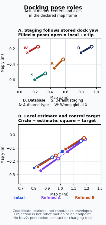
An independent checker recovered each pose from the centers of the prism’s near and distal faces, then expressed it in the declared map frame. The entire setup had a common nonplanar rigid rotation and translation in Blender world, so the comparison used reconstructed frame coordinates rather than treating world x as dock-local x.
| Staging construction | Measured displacement in database-local x/y | Heading change from database |
|---|---|---|
| Examined default offsets | Approximately (−700, 0) mm | Approximately 0° |
| Authored alternate offsets | Approximately (−400, 0) mm | Approximately +15° |
The alternate marker’s heading changed by 15° while its position remained on the original dock’s negative local x axis. This is the distinction the staging formula requires: orientation offset and displacement direction are separate. By contrast, subtracting 0.70 m only from map x placed the incorrect marker approximately 362.35 mm from the default staging position in this constructed 30° case. That is an error between two coordinate constructions, not measured docking error on a robot.
We then deliberately assigned two new local estimates. They were prescribed values, not detection or filter results. The actual database and staging markers remained unchanged while the local-estimate and controller-target matrices changed.
| Local-estimate state | Prescribed map x/y | Prescribed yaw | Measured target projection length |
|---|---|---|---|
| Initial copy | (0.80, −0.25) m | 30° | Approximately 250.0 mm |
| Refinement A | (0.85, −0.27) m | 35° | Approximately 250.0 mm |
| Refinement B | (0.83, −0.24) m | 32° | Approximately 250.0 mm |
For all three states, the measured target displacement followed the current local estimate’s x axis, with a transverse component that rounded to zero at the displayed precision. Changing the estimate therefore changed where the projected target lay in the map, even though its local 0.25 m relationship remained the same. The database pose and staging pose did not follow that update.
The independent check covered five complete captures: the initial state and before/after geometry for each of the two updates. Those are repeated observations of six markers, not five docking trials. The rounded numbers describe the constructed mesh geometry; their small floating-point residuals do not establish sensor precision, docking accuracy, control performance or physical clearance. No trajectory, contact, charging or hardware outcome was measured.
Capture each pose where its role changes
For a confusing docking log or visualization, capture one labeled sequence for the same request. Keep the frame and timestamp with every pose, and transform values into one reference frame before comparing positions or yaw.
- Request and lookup: record
use_dock_id, the requested instance key or explicit pose, the selected type and loaded plugin implementation. Record the optional pluginidseparately. - Stored or supplied dock pose: record its x, y, yaw and frame before staging or refinement. This is the baseline for detecting an actual record change.
- Staging output: record the plugin’s output plus
staging_x_offsetandstaging_yaw_offsetwhen that implementation uses them. Check translation along the original dock yaw separately from the staging heading. - Local refinement input and output: record the estimate in the fixed frame, external-detection mode, return value, and pose before and after each call. For enabled detection, also record received pose time/frame, age, filter output and configured offsets.
- Controller target: record the local refined pose, the projected pose before base-frame conversion, and the final base-frame target. Include docking direction and any rotation branch so that an orientation adjustment is not mistaken for a perception jump.
- Termination evidence: record the plugin’s
isDocked()andisCharging()results and the configuration or sensor signal behind them. A successful refinement call belongs in a different column from either success signal.
This sequence helps locate the first stage where your intended geometry and the runtime output diverge. If the stored record is stable while the detected and refined poses change, investigate perception, frames and plugin offsets first. If staging is wrong before detection starts, inspect the instance/type selection and staging calculation instead.
A plausible pose does not establish contact or charging
The ChargingDock interface separates pose refinement from isDocked() and isCharging(). The server’s approach termination and charging wait make those separate checks visible in the control flow. Returning true from refinement does not prove contact, convergence or electrical charging.
Even those method names need implementation context. In the examined SimpleChargingDock checks, isDocked() can use stall detection or a configured distance threshold. isCharging() uses battery-status information when enabled and otherwise falls back to isDocked(). A true return from a geometric fallback is not an independent current measurement.
Once the pose roles and success signals are understood, the separate AMR auto-docking performance test guide covers physical acceptance trials involving contact, charging, retries and operating conditions. The coordinate experiment here executed none of those systems or outcomes. It made the stored pose, derived staging pose, mutable local estimate and projected control target distinguishable; each still needs its own frame, timestamp and meaning when you interpret a real docking log.