One robosuite environment action can span several simulation steps, but that does not mean the same actuator command is held for all of them. In the examined robosuite v1.5.2 fixed-base path, the environment marks the first internal pass as a policy step, the robot updates its goal on that pass, and the controller still runs on every internal pass. Debug the three events separately: action arrival, goal update, and controller evaluation.
That distinction matters when a robot moves differently from what you expected. A slice error can send values to the wrong part, a delta rule can build the wrong goal, and a cadence misunderstanding can make a correct goal look stale. Changing gains before identifying which layer failed mixes three different problems.
The implementation details below are pinned to robosuite release v1.5.2, commit 824ac14cefcfb7ec125fe5eb2e0bad7364466154. They describe the inspected RobotEnv and FixedBaseRobot path at that pin. They are not a promise about another release, another robot class, an installed configuration or hardware timing. No robosuite, MuJoCo, controller or robot runtime was executed for this article.
One environment step contains more than one controller call
The environment first establishes two different intervals. In MujocoEnv.initialize_time(), model_timestep comes from the simulation timestep setting, while control_timestep is computed as 1 / control_freq. These values answer different questions: how far the physics model advances per internal step, and how long one environment control interval lasts.
The pinned step() loop runs int(control_timestep / model_timestep) internal passes. It starts with policy_step=True, passes the supplied action into _pre_action() on every pass, and changes the flag to false after the first pass. This is a call schedule, not evidence that every controller output remains numerically constant.
For an exact illustrative ratio, a 0.10-second control interval divided by a 0.02-second internal step gives five passes. The schedule is then:
| Internal pass | Supplied environment action | policy_step |
Question to log |
|---|---|---|---|
| 0 | Same current action | True |
Was a new goal accepted? |
| 1–4 | Same current action | False |
What reference and state did the controller evaluate? |
Those numbers are an authored example, not robosuite defaults or a recommended configuration. The source uses an integer conversion for the loop count, so this article does not generalize the illustration to a non-integer ratio.
Trace the action through the fixed-base path
The meaning of policy_step becomes useful only after following the call chain. The examined RobotEnv._pre_action() checks and splits the flat action, then calls each robot’s control() method with its routed action and the current policy_step flag.
That makes action ownership the first prerequisite. If you have not established the named slices, use the robosuite composite-action layout guide before investigating cadence. Repeatedly sending the wrong slice is still a routing fault.
Inside the inspected FixedBaseRobot.control(), the sequence is more specific:
- The robot updates its current state on every call.
- It calls
set_goal(action)only whenpolicy_stepis true. - It calls
run_controller()for enabled parts on every call. - It clips the resulting torques or controls to actuator bounds and assigns them.
The practical result is precise: a new environment action is not the same event as a controller output calculation. Goal setting is gated in this path; controller calculation is repeated. Because state is also refreshed, later substeps can produce different outputs even when no new goal is supplied.
The inspected part-controller configuration supplies the robot control frequency as policy_freq when constructing the part controller. That fact does not make policy_freq, observation sampling, wall-clock scheduling and a physical device loop interchangeable. Record each configured value and the code path that consumes it.
Build a small configuration ledger before reading a plot or a controller log:
| Name in the trace | Where it comes from | What it establishes here |
|---|---|---|
model_timestep |
Environment time initialization | Duration assigned to one internal physics step |
control_timestep |
Reciprocal of environment control_freq |
Duration assigned to one environment action interval |
policy_step |
First-pass flag inside step() |
Whether the inspected fixed-base path may call set_goal() |
Controller policy_freq |
Part-controller construction | Configuration supplied to that controller, not proof of a measured runtime rate |
Then test one claim at a time. If an action ID changes every five internal indices but the goal changes at a different index, inspect dispatch and the policy_step flag. If the goal changes only at the expected boundary but the intermediate reference changes within the interval, inspect interpolation rather than action delivery. If both are correct but the assigned controls flatten at a bound, compare the raw controller output with the post-controller clipping stage. These observations localize a branch; none measures real-time latency by itself.
A held goal is not necessarily a held reference
It is tempting to summarize the loop as “the goal is held for five physics steps.” That wording is safe only if “goal” means the value supplied through set_goal() in the inspected path. It says nothing universal about the controller’s intermediate reference or its final actuator command.
An enabled interpolator may turn one supplied goal into changing intermediate references. A controller can also react to the refreshed state at each call. The actuator-range clipping occurs after run_controller(), so a repeated call can produce a different clipped assignment even though set_goal() did not run again.
There is another scope boundary in the same source file. The base MujocoEnv._pre_action() default writes the action directly to simulation controls. The goal-gating explanation therefore belongs to the inspected RobotEnv plus FixedBaseRobot dispatch, not every subclass of MujocoEnv.
If your command is a delta, cadence comes after reference semantics. The OSC delta-target guide asks whether a delta is applied to achieved position or to a prior desired goal. That article uses a different source pin. Here the question is narrower: once the selected implementation has formed a goal, when is that goal refreshed and what runs between refreshes?
Log six events before changing gains
A useful trace needs boundaries, not one “control rate” column. For two consecutive environment actions, capture these fields with a monotonic sample index:
- Environment action ID and its arrival at
step(). control_timestep,model_timestepand the resulting internal-pass count.- Internal-pass index and the actual
policy_stepflag. - Routed action slice for the selected robot part.
- Whether
set_goal()ran, plus the supplied goal and any intermediate reference as separate values. - Current state, raw controller output, actuator-bound clipping and assigned control as separate stages.
Interpret the trace in that order. If the named slice is wrong, fix routing. If the slice is right but the newly set target is wrong, inspect absolute-versus-delta semantics and the target’s reference state. If the goal is correct but the intermediate reference differs, inspect the configured interpolator. Only after those checks should gains or actuator limits become the main suspect.
Also record the exact class that owns _pre_action() and control(). A log labeled only “robosuite controller” cannot distinguish the base direct-control path from the fixed-base goal-setting path. Include controller type, enabled body parts, interpolation setting and actuator bounds beside the timing fields. That makes the trace reproducible without treating one class-specific call sequence as a library-wide rule.
Do not infer latency or effective bandwidth from the ratio alone. The two configured intervals do not measure scheduling jitter, computation time, observation age, network delay or hardware response. They describe the examined loop structure.
Actual finite markers separate the two rules
To make the distinction visible, S1 created two isolated cases in Blender 5.2.2 LTS. Each case contains ten separately authored static rows, with a finite rail, state prism, supplied-goal marker and intermediate-reference marker in every row. Across both cases, the actual capture contains 80 unshared closed prisms and 640 evaluated world-space vertices. These are geometric illustrations; no robosuite or MuJoCo rollout was run.
Both cases use the same prescribed state positions and interval goals. The authored state x increases from 0.060 m to 0.150 m in ten samples. The goal is 0.180 m for the first five samples and 0.080 m for the next five. Authored time labels advance by 0.020 s; the goal-update flag is true at labels 0.000 s and 0.100 s. These labels and flags are inputs, not measured timestamps or observed controller calls.
In the held case, the reference marker equals the supplied goal. In the second case, the reference follows an explicitly authored linear rule: weights 1/5 through 5/5 from the prior reference to the current goal. The first interval begins from 0.060 m; the second begins from the previous goal, 0.180 m. This rule demonstrates a possible intermediate-reference distinction, not robosuite’s configured interpolator.
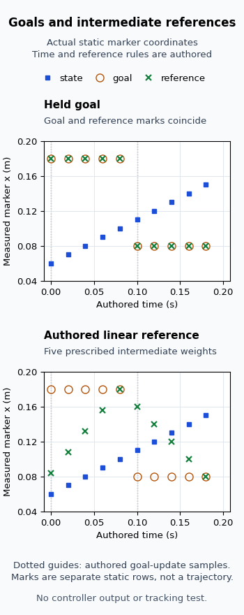
Selected actual recovered x coordinates, rounded to six decimal places, are:
| Authored time (s) | State marker x (m) | Supplied goal x (m) | Held reference x (m) | Authored linear reference x (m) |
|---|---|---|---|---|
| 0.000 | 0.060000 | 0.180000 | 0.180000 | 0.084000 |
| 0.080 | 0.100000 | 0.180000 | 0.180000 | 0.180000 |
| 0.100 | 0.110000 | 0.080000 | 0.080000 | 0.160000 |
| 0.180 | 0.150000 | 0.080000 | 0.080000 | 0.080000 |
The independently recovered goal coordinates change once between adjacent rows, at the interval boundary. Within each five-row interval, the goal and held reference have zero x changes above the fixed 0.000008 m comparison allowance. The authored linear reference changes at all eight within-interval transitions. Those counts distinguish the two prescribed rules; they do not establish a controller’s behavior.
At the first sample, the measured x-only separation between reference and state is 0.120000 m in the held case and 0.024000 m in the authored linear case. At the start of the second interval it is 0.030000 m versus 0.050000 m. Neither is a tracking-error measurement: the state sequence was prescribed independently, no feedback was simulated, and the markers have different y and z offsets. An x projection is also not a three-dimensional clearance or collision test.
The independent checker reconstructed every prism’s eight corners, outward faces, normals and proper common-frame transform, then recovered the marker centers and removed the declared display-row offset from y. It compared the authored schedule separately using rational arithmetic.
Use this result to keep a debugging trace’s columns separate. The source trace tells you where goal updates and controller evaluations occur in the inspected fixed-base path. The finite markers explain how an unchanged supplied goal can coexist with a changing intermediate reference. Only logs from your actual configured controller can determine its references, outputs and state response. This experiment measures static geometry, not controller quality, tracking, dynamics, collision behavior, latency, bandwidth, hardware timing or safety.