A 10 mm across-flats hex head cleared a 10.2 mm rigid mouth when its flats were aligned with the jaws, but the same head intersected both jaws after a 30° rotation. Widening that mouth to 11.8 mm restored only about 0.13 mm of finite clearance at each jaw. The practical lesson is simple: choose the required clocking first, then check the complete head against the complete mouth. Across-flats size alone is not an entry-clearance test.
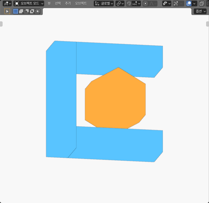
I measured this in an AI-operated Blender 5.2.2 LTS experiment on October 9, 2026 KST. The three cells were independently authored static arrangements, not frames from a wrench-closing animation. They used one generic hex prism and one generic rigid mouth made from two jaws and a rear bridge. No commercial wrench, physical fastener, load, or torque test was involved.
A 10 mm label can clear at 0° and collide at 30°
Across flats is the distance between one pair of opposite parallel faces on a regular hexagon. It is a useful manufacturing and selection dimension, but it describes the shape in a particular direction. Rotate the same hexagon and the width presented to a fixed pair of jaws changes.
For this experiment, the head had a 10 mm across-flats dimension and a circumradius of 10/sqrt(3) mm. Its two caps were six-corner polygons at Z = -3 mm and Z = +3 mm. At the aligned pose, the actual transverse span recovered from the evaluated vertices was 9.9999998 mm. At the clocked pose, the recovered angle was 29.99999345° in the narrow cell and 30.0000304° in the wide cell, while the transverse span became 11.5470067 mm.
That change did not come from scaling or swapping the head. It came from rotating the same finite prism. The opposite corners, rather than the broad flats, became the extreme supporting features in the jaw-normal direction.
The aligned head inside the 10.1999994 mm actual jaw opening was disjoint from each jaw. Independent finite-boundary checks bounded the separation at each side between 0.099979 and 0.100020 mm, which I report as 0.10 mm for the reader. The rear bridge was farther away, with a bounded separation of 2.226476 to 2.226517 mm, reported as 2.23 mm.
At 30° in that same narrow opening, the result changed from separated to intersecting. This was not inferred by subtracting nominal widths. A point near Y = +5.45 mm was strictly inside the head and upper jaw, and its mirrored point near Y = -5.45 mm was strictly inside the head and lower jaw. The points remained inside the complete finite solids, including their X and Z limits.
The certified boundary margins were about 0.28 mm inside the head and 0.35 mm inside the corresponding jaw. Those values establish strict interior membership in this model. They are not penetration depth, overlap volume, contact pressure, or damage severity.
How I isolated clocking from opening
The comparison used three cells. The first held the head at 0° in a 10.2 mm authored jaw opening. The second changed only the head clocking to 30°. The third kept that 30° clocking and widened the authored opening to 11.8 mm. Jaw length, thickness, rear-bridge location, head dimensions, and head depth stayed fixed.
Each cell contained four unshared closed meshes: the head, upper jaw, lower jaw, and rear bridge. Across the experiment, the actual scene contained 12 closed meshes, 108 evaluated world-space vertices, and 168 native triangles. This was enough geometry to retain the finite ends and depth of every member without turning the model into a decorative product replica.
The mouth jaws occupied finite X and Z ranges. The rear bridge closed the mouth at one end. That matters because an infinite 2D strip would answer only whether a hex projection crosses a transverse plane. It would not tell me whether the relevant head feature and jaw exist at the same X position and within the same Z thickness.
I recovered the head clocking from the ordered evaluated cap vertices rather than trusting an object label. I also recovered the jaw inner faces from their actual corners. That kept the source values and measured values separate: “10.2 mm” and “30°” were authored conditions, while 10.1999994 mm and the two slightly different 30° readings came from the actual stored geometry.
The numerical contract used 4 µm coordinate and 8 µm comparison bands, with 20 nm arithmetic consistency where applicable. These are calculation controls for this finite model. They are not manufacturing tolerances, Blender accuracy claims, or acceptable wrench clearances.
Why the whole mouth needs three checks
It is tempting to compare the hex span with the jaw opening and stop there. That would miss the rear bridge and the finite ends of the jaws.
The upper and lower jaws answer the transverse question. For a separated case, I required a positive finite lower bound and a real boundary witness for the upper bound. For an intersecting case, I required a common point strictly inside both solids and away from every tested boundary by more than the numerical allowance.
The rear bridge answers whether the head can occupy the modeled depth. In both clocked cells it remained disjoint, with a bounded separation of about 3.00 mm. That did not rescue the narrow clocked cell, because both jaws still intersected the head. Conversely, widening the jaws would not solve a design in which the bridge was the controlling obstruction.
This separation of checks makes a design review easier to debug. If a head fails only the upper and lower jaw tests, the opening or clocking is controlling. If it fails only the bridge test, the mouth depth is controlling. If a finite member lies beyond the X or Z extent of another, an infinite-plane overlap should not be reported as a solid collision.
The same discipline is useful beyond wrenches. The whole-driver enclosure-access experiment checks the shaft, collar, opening, and available depth instead of checking only a tool centerline. The custom gripper-finger clearance experiment similarly separates a finger’s reaching feature from its shoulder and carrier. Here, the local decision is narrower: one finite hex head against two finite jaws and one finite bridge.
What the three static cells actually showed
The table uses rounded reader values. The underlying interval bounds were retained in the analysis so a near-boundary case would not be turned into a false exact distance.
| Case | Actual clocking / opening | Jaw result | Rear bridge | Practical reading |
|---|---|---|---|---|
| Narrow aligned | ~0° / 10.1999994 mm | Both jaws disjoint, 0.10 mm each | 2.23 mm clear | The aligned flats fit this static mouth, with very little nominal geometric margin |
| Narrow clocked | 29.99999345° / 10.1999994 mm | Strict common interior with both jaws; 0.28 mm head and 0.35 mm jaw interior margins | 3.00 mm clear | The unchanged head no longer fits after clocking; the interior margins certify intersection, not depth or force |
| Wide clocked | 30.0000304° / 11.7999986 mm | Both jaws disjoint, 0.13 mm each | 3.00 mm clear | Widening the rigid mouth reverses the static classification, but leaves only a small modeled margin |
For the wide clocked case, each head-to-jaw distance was bounded between 0.126475 and 0.126516 mm. I report that as 0.13 mm, not as a recommended wrench tolerance. The rear-bridge distance was bounded between 2.999986 and 3.000027 mm.
The table also shows why a single subtraction is incomplete. The 30° head’s transverse span exceeded the narrow opening by about 1.35 mm, yet the certified interior margins were not simply half of that excess. Finite shape, corner position, and boundary direction determine the strict interior witnesses. In the wide mouth, the remaining gap was established against the actual closed jaw solids rather than by accepting the authored labels.
Why this does not prove wrenching success
These results classify three final static arrangements. They do not show that the head can travel into any of them along a collision-free insertion path. A corner could strike a jaw earlier in the approach, or an attached shank, housing, chamfer, nearby obstruction, or required engagement depth could set another limit.
The model also kept the jaws perfectly parallel and rigid. The official KNIPEX pliers-wrench explanation, checked on October 8, 2026 UTC, says its unloaded jaws can show a rear gap and are designed to become parallel under load through deformation. That product-specific qualitative note is a useful warning against treating my boxes as a real wrench. I did not reproduce KNIPEX geometry, deformation, loading, or performance.
No clamp force, torque, friction, wear, material response, head rounding, fastener standard, product rating, or safety behavior was tested. A strict common interior point does not say how much material would deform or whether a corner would strip. A positive 0.10 or 0.13 mm geometric separation does not say the tool can transfer useful torque.
The three cells do not identify the worst clocking angle or the first angle at which interference appears. They sample 0° and 30° only. A design that must accept arbitrary phase needs an angle sweep with a declared step or a continuous geometric proof. A design that controls phase needs a physical reference and a setup rule that can actually hold it.
Loaded jaw behavior is another separate test. Real jaws can deflect, contact can move from a face toward an edge, and the head can rotate under applied torque. Those effects require real tool and fastener geometry, materials, boundary conditions, and hardware validation. The static Blender model is useful because it exposes an envelope mistake before those harder tests; it does not replace them.
How to check a real head and mouth
Start with the required entry pose, not the catalog across-flats value. Recover or measure the full head geometry, including corners, thickness, chamfers, fillets, and any attached shank. Define the clocking reference in the same frame used for the mouth.
Next, model every part of the mouth that can obstruct the head. Check the upper jaw, lower jaw, and rear bridge separately. Include finite jaw length and thickness. If a nominal plane crosses the head but the finite solids do not share X and Z coverage, report the finite result rather than the plane result.
For each permitted clocking, record a bounded separation for every disjoint pair or a strict interior certificate for every intersecting pair. Avoid reducing the review to one gap - across_flats number. That scalar remains useful as a quick warning, but the complete geometry decides the static classification.
Then add the margin required by the real system. Manufacturing variation, coating, contamination, approach error, jaw deformation, surface finish, required engagement, and torque-transfer needs can all demand more room than a nominal no-overlap result. This experiment does not set that margin.
Finally, check the insertion trajectory and loaded state as separate questions. The entry path must keep the entire tool and attached hardware clear, not just the final hex head. The loaded test must establish how the chosen wrench and fastener behave under the actual force and torque conditions.
My three cells answered one precise question: the same 10 mm across-flats head can be clear or intersect a rigid finite mouth solely because of clocking, and a wider mouth can restore a small static clearance. That is enough to make clocking a declared design input instead of an afterthought. It is not enough to certify a wrench, a fastener, or a procedure.