For a narrow neck between wider shoulders, choose finger reach before increasing pad height. In the geometry below, a 12 mm reach keeps the taller carrier 2 mm outside each shoulder at final closure. A centered 12 mm tall pad also leaves 2 mm above and below the gripping band. That combination offers a 96 mm² planar contact patch per jaw; a taller pad can hit the shoulders without gaining any usable neck surface.
On October 5, 2026, we ran this AI-operated virtual comparison in Blender 5.2.2 LTS and independently checked its actual world-space mesh coordinates. No physical gripper was operated.
The pad reaches the neck, but what follows it?
A jaw opening equal to the neck width describes where the two inner contact faces finish. It says little about the material behind those faces. On a shouldered part, a tall carrier can overlap a flange even when a short pad sits neatly inside the recessed band.
Custom fingertips are a practical way to accommodate unusual part geometry. Robotiq’s design guidance explicitly calls for adequate clearance through the full stroke and checking part shape, overhang and stroke range. The dimensions here belong to a generic comparison rather than a design for one of its grippers. Robotiq’s custom fingertip guidance.
The example uses a rectangular part with a 40 mm wide neck. Its lower and upper shoulders are 60 mm wide, protruding 10 mm beyond each neck face. The recessed band runs from height 6 mm to 22 mm, giving a 16 mm vertical opening. The neck is 30 mm deep; each finger is 8 mm deep and centered on it.
Each finger has a horizontal pad connected to a taller, 5 mm wide carrier. The carrier continues upward to a palm above the part. Both jaws close symmetrically from a 48 mm opening to a 40 mm opening. The part remains centered and fixed, so the comparison isolates finger shape and placement. The palm is a fixed reference block; slides, actuation and mounting hardware are not modeled.
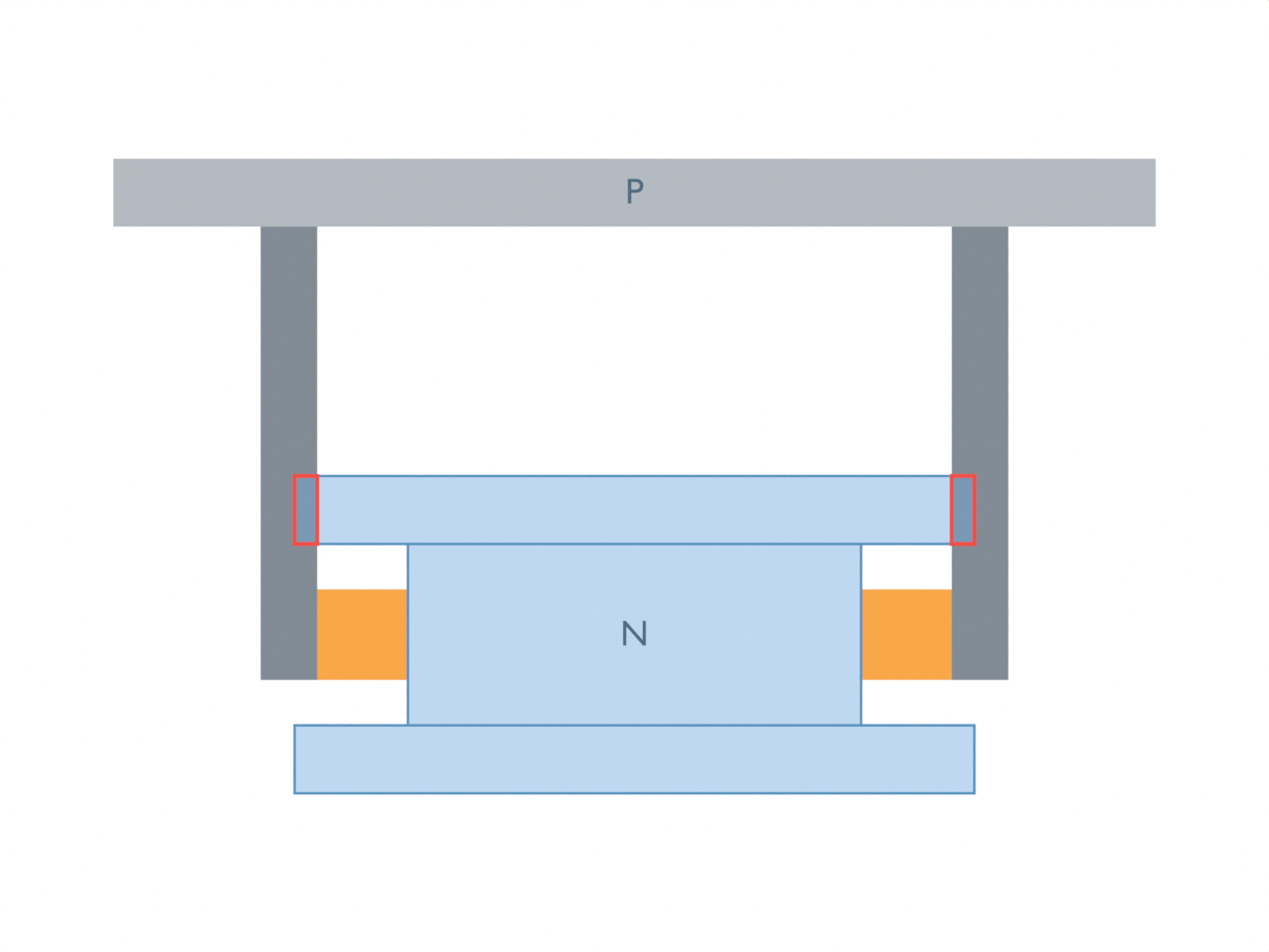
Blue represents the part; orange marks the pads, dark gray the carriers and light gray the palm. N and P identify the neck and palm. The part is transparent and outlined in this front orthographic view. Red outlines project the audited solid intersections to the front for visibility; they are display overlays, not simulated contact forces.
Set reach from the shoulder’s protrusion
Let the neck width be Wn, shoulder width Ws, and pad reach p, all in millimetres. Reach is the horizontal distance from the pad’s inner face to the carrier’s inner edge. At final closure, the carrier clearance on either side is
c = p − (Ws − Wn) / 2.
For this part, c=p−10 mm. An 8 mm reach leaves a negative 2 mm balance: the carrier crosses into the shoulder’s volume. A 10 mm reach puts its inner edge exactly on the shoulder edge. A 12 mm reach gives a positive 2 mm gap.
The closing path matters. At the initial 48 mm opening, the 8 mm reach has 2 mm of carrier clearance. Halfway through closure it touches the shoulder; thereafter it intersects. An unobstructed starting pose therefore does not establish a clear closing stroke.
A desired geometric carrier gap g gives the useful sizing rule p≥(Ws−Wn)/2+g. Here, choosing g=2 mm leads to p≥12 mm. This allowance is an explicit input to the model, not a manufacturing tolerance recommendation.
Fit pad height inside the band
Let pad height be h and its center height be z. The pad occupies [z−h/2, z+h/2]. For strictly positive vertical clearance from both shoulders, require
6 < z − h/2, and z + h/2 < 22.
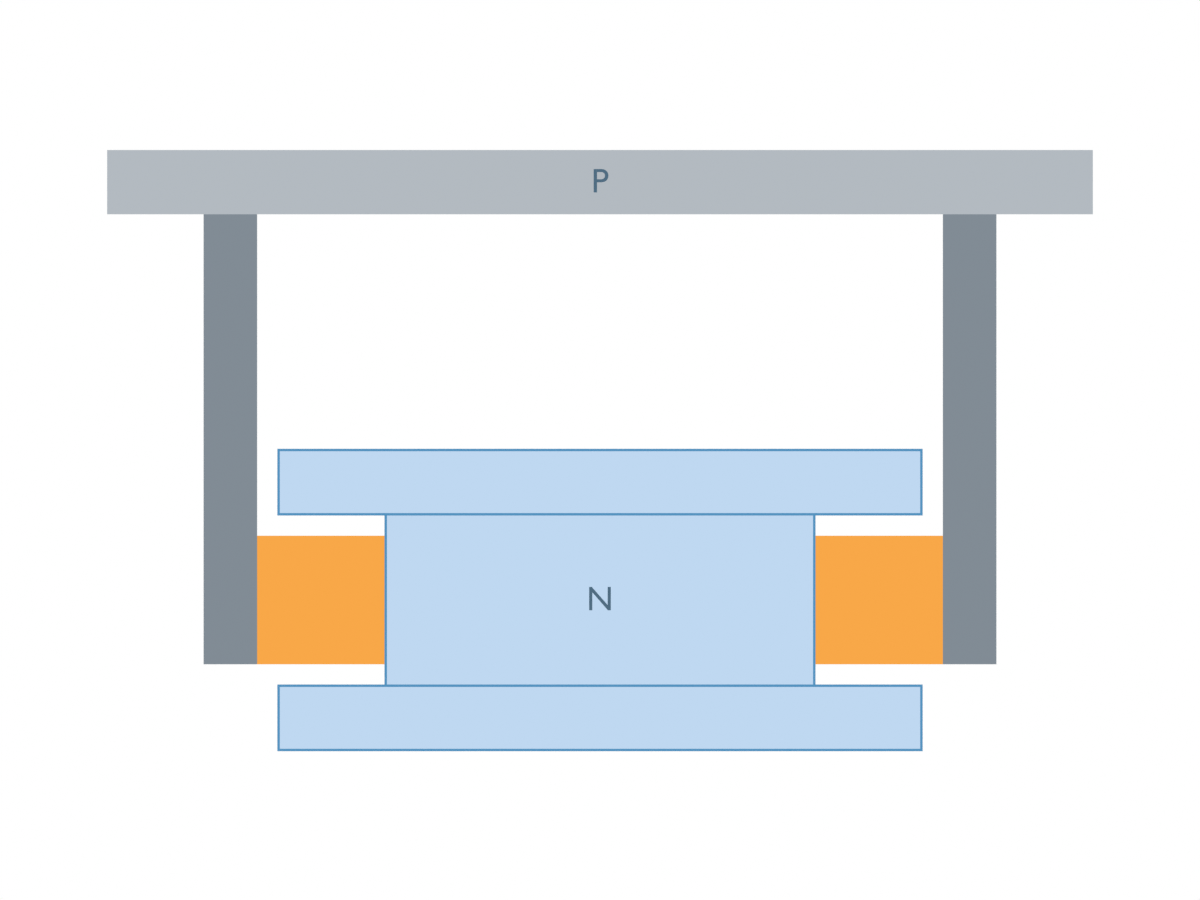
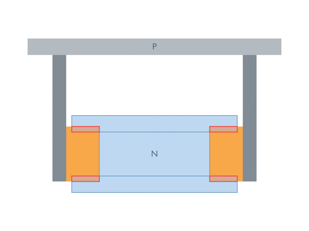
Centering at z=14 mm makes the two vertical gaps equal. An 8 mm pad spans 10–18 mm and leaves 4 mm at each end. A 12 mm pad spans 8–20 mm and leaves 2 mm. A 16 mm pad spans the entire band and touches both shoulders. A 20 mm pad extends 2 mm into each shoulder.
Vertical placement can undo a suitable height. Move the 12 mm pad’s center from 14 mm to 18 mm and its upper edge reaches 24 mm, overlapping the upper shoulder by 2 mm. The pad is unchanged; the geometry of its position causes the obstruction.
Count neck surface that the pad can actually cover
For a rectangular neck and aligned planar pad face, the available contact patch at closure is finger depth times the pad’s vertical overlap with the neck:
A = 8 × max(0, min(z + h/2, 22) − max(z − h/2, 6)) mm².
The centered 8 mm pad covers 64 mm² per jaw. Increasing it to 12 mm raises the patch to 96 mm² while retaining positive vertical clearance. At 16 mm, the patch reaches the neck’s 128 mm² maximum, but shoulder clearance becomes zero. The 20 mm pad still covers only 128 mm² of neck and also intersects both shoulders. Its added height provides no added neck patch.
The shifted 12 mm pad covers only 10 mm of the band, giving 80 mm² per jaw, while also overlapping the upper shoulder. These areas describe geometric surface coincidence. They do not measure holding force.
Keep positive clearance, touch and interference separate
The native study sampled 101 inclusive closing positions for each of seven variants, giving 707 measured poses. The table counts shoulder interactions of the complete pads and carriers; planned pad/neck face contact at closure is treated separately.
| Case: reach / pad height / center height (mm) | Clear poses | Touch poses | Interference poses | Neck patch per jaw at closure (mm²) |
|---|---|---|---|---|
| A: 8 / 8 / 14 | 50 | 1 | 50 | 64 |
| B: 10 / 8 / 14 | 100 | 1 | 0 | 64 |
| C: 12 / 8 / 14 | 101 | 0 | 0 | 64 |
| D: 12 / 12 / 14 | 101 | 0 | 0 | 96 |
| E: 12 / 16 / 14 | 0 | 101 | 0 | 128 |
| F: 12 / 20 / 14 | 0 | 0 | 101 | 128 |
| G: 12 / 12 / 18 | 0 | 0 | 101 | 80 |
An independent script reconstructed all eight solids from their stored local vertices and world matrices, checked their six support faces, and rechecked the pad/carrier intersections and interior witnesses. It also checked the four vertex indices of each pad’s inner contact face and its available neck area. The greatest coordinate discrepancy from the prescribed geometry was about 0.00000371 mm. The 0.0001 mm numerical readback tolerance distinguishes intended equality from tiny floating-point differences; it is not a fabrication allowance.
Positive clearance, exact touch and interior intersection are different outcomes. The 10 mm reach finishes with no positive carrier reserve, despite avoiding modeled penetration. Similarly, the 16 mm pad covers the full neck height by touching its shoulder boundaries. Counts are sampled configurations, not time, probability or holding reliability. The independent analytic boundary controls also tested both sides of the carrier-reach, pad-height and vertical-placement equality limits.
The useful decision is therefore structural: provide enough reach to clear the carrier, then choose pad height and placement inside the remaining band. This model covers aligned rigid boxes and a prescribed closing path. It does not include friction, compliance, load, dynamics or a hardware grip test; those determine how an eligible geometry performs in service.
For the separate question of whether an object is centered inside the jaw opening, see our gripper aperture and object-centering study. That establishes the target contact faces; this comparison checks the larger finger structure following them.