In the actual Blender geometry, the 80 mm output arm produced about 27.36 mm of useful tangent travel at ±20°, while the 50 mm input arm produced about 17.10 mm. The longer arm also had more radial drift: about 4.82 mm versus 3.02 mm. Both components scaled by the same 1.6 arm-length ratio. A longer bell-crank arm therefore gives more endpoint travel, but it also asks a guide, slot, joint, or surrounding frame to accommodate more sideways departure.
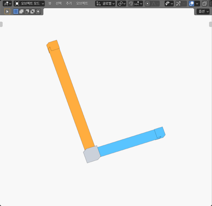
This was an AI-operated Blender 5.2.2 LTS experiment with three independently authored static poses at -20°, 0°, and +20°. It was a virtual geometry measurement, not a physical bell crank, actuator, or load test. The model had two perpendicular rectangular arms, finite endpoint markers, and a pivot reference. Those boxes made the endpoint frames measurable; they did not represent bearings, pins, or a working assembly.
The longer arm increased travel and drift together
The generic crank used a 50 mm input arm along local +X and an 80 mm output arm along local +Y. Both belonged to one rigid 90° frame rotating about local Z. At the zero pose, the input endpoint sat on +X and the output endpoint sat on +Y.
For an ideal arm of length L, rotation by θ moves the input endpoint to (L cos θ, L sin θ). Relative to zero, its useful tangent displacement along +Y is L sin θ, while its radial departure along +X is L(cos θ - 1).
The output endpoint begins on +Y, so the same rotation moves it to (-L sin θ, L cos θ). Its natural tangent axis is -X, making its useful tangent displacement L sin θ. Its radial departure along +Y is again L(cos θ - 1).
Those axis choices matter. If the output’s world X coordinate were compared directly with the input’s +Y coordinate, the signs would appear opposite even though both endpoints advance in their own positive working directions for positive rotation. I defined input +Y and output -X as the tangent axes, then input +X and output +Y as the radial axes.
The actual ±20° measurements followed the expected structure. Rounded to reader values, the input tangent displacement was -17.10 mm at -20° and +17.10 mm at +20°. The output values were -27.36 mm and +27.36 mm. The input moved inward by about 3.02 mm along its radial axis at either outer pose; the output moved inward by about 4.82 mm.
The ratio was not selective. Dividing either output tangent magnitude by the matching input tangent magnitude gives about 1.6. Dividing the radial magnitudes gives the same result. The longer arm increased useful travel and lateral drift together because both are proportional to arm length for the same rigid rotation.
Three static poses kept the comparison controlled
Only the crank angle changed between the three cells. Arm lengths, cross-sections, endpoint markers, pivot reference, and the 90° relationship stayed fixed. Each cell contained five unshared closed boxes: the input arm, output arm, two endpoint markers, and the pivot reference.
The complete actual model contained 15 closed meshes, 120 evaluated world-space vertices, and 180 native triangles. The three cells were authored separately rather than generated as animation frames. That choice made each pose an independent geometry sample, but it also means the experiment did not observe continuous movement between them.
The arm and reference boxes intentionally overlap at schematic joints. Those overlaps are not collision failures. The pivot box is a finite marker for the mathematical center, not a pin or bearing. The endpoint boxes are reference markers, not sliders that force straight travel.
The three cell origins were separated by 200 mm to keep them readable in the Blender viewport. I removed that display translation before comparing endpoints. The spacing is not mechanism travel, frame size, or a third link.
This reader job differs from the slider-crank and Scotch-yoke timing experiment, which compares equal linear strokes and near-end dwell. It also differs from the tool-side compliance slide-direction experiment, which projects equal slide strokes onto one oblique surface normal. Here, one rigid rotating member has two unequal arms, and each endpoint is resolved into its own tangent and radial components.
Three samples answer a useful first question: how much did the endpoints move at these authored angles? They do not identify the maximum drift over an entire operating range, the first interference with a frame, or a permissible continuous path.
I measured finite endpoints rather than trusting labels
The actual endpoint locations came from the mean of all eight evaluated corners of each endpoint marker. The pivot came from the same all-corner method. I also recovered each arm independently from the means of its finite start and end faces, then checked the arm lengths, perpendicular directions, and common rotation frame.
That distinction matters because the metadata said 50 mm, 80 mm, and ±20°, but labels are inputs, not measurements. The evaluated geometry contained small floating-point differences. The actual arm-length ratio remained bounded at about 1.6, and the recovered angles remained near the authored poses, but the positive and negative coordinates were not byte-for-byte mirror images at every last digit.
I kept that asymmetry rather than replacing it with ideal values. Reader results are rounded to two decimal places because the design question does not benefit from long floating-point tails. The independent records retain outward intervals around the measured values.
The input’s zero-to-outer-pose endpoint chord measured about 17.36 mm, and its -20° to +20° chord measured about 34.20 mm. The output equivalents were about 27.78 mm and 54.72 mm. These are straight distances between sampled endpoint centers, not arc lengths.
The chord ratio also follows the arm-length ratio. For an ideal rigid rotation, the zero-to-pose chord is 2L sin(|θ|/2), and the -20° to +20° chord is 2L sin 20°. The actual geometry was used to measure the values; the formulas were a separate cross-check.
The numerical process used coordinate and comparison allowances to distinguish meaningful geometry from stored floating-point noise. Those bands describe consistency inside this model. They are not machining tolerances, mounting accuracy, backlash, or a recommendation for how closely a physical crank should be built.
What the three measured poses showed
The table reports rounded values in millimetres. Tangent signs use input +Y and output -X. Radial departure uses input +X and output +Y, so negative values indicate inward motion from the zero-pose radial reference.
| Pose | Input tangent / radial | Output tangent / radial | Endpoint chord from zero | Reader interpretation |
|---|---|---|---|---|
| -20° | -17.10 / -3.02 mm | -27.36 / -4.82 mm | 17.36 / 27.78 mm | Both endpoints moved in the negative tangent direction while drifting inward; output magnitudes were about 1.6× input |
| 0° | 0.00 / 0.00 mm | 0.00 / 0.00 mm | 0.00 / 0.00 mm | This pose defined the recovered pivot and endpoint axes; the -20° to +20° chords were 34.20 / 54.72 mm |
| +20° | +17.10 / -3.02 mm | +27.36 / -4.82 mm | 17.36 / 27.78 mm | Tangent direction reversed, radial departure remained inward, and both components retained the arm-length scaling |
The zero row is a reference, so a ratio of output displacement to input displacement is undefined there. It should not be reported as zero, one, or 1.6. The 1.6 comparison applies to corresponding nonzero displacement magnitudes and to the recovered arm lengths.
The rounded symmetry in the table is appropriate for the reader decision, but it should not be mistaken for exact binary symmetry. The evaluated positive and negative poses differed slightly at deeper precision because the geometry was stored and transformed with finite floating-point values.
The outer-to-outer chords provide another practical view. They tell me the direct separation between the two sampled endpoint locations. They still do not tell me the swept arc length, the space occupied by the complete arm between samples, or whether another component can follow that movement.
Static displacement is not force or function
The current official context is Carnegie Mellon University’s Chapter 2 mechanism notes, checked from the retained anonymous HTTP 200 source on October 8, 2026 UTC. The chapter discusses mechanism geometry and relative motion in the broader context of machines that transmit force. It does not provide this bell-crank geometry, dimensions, arm ratio, force formula, product example, or performance result.
This Blender experiment stays with geometry. It does not calculate mechanical advantage, input force, output force, torque balance, shaft load, bearing reaction, arm stress, stiffness, fatigue, backlash, friction, or efficiency. A longer output arm can change a moment relationship, but that statement needs a defined force direction, load point, and equilibrium model that are absent here.
The boxes also do not demonstrate a physical joint. There are no holes, pins, bushings, fasteners, welds, clevises, or bearings. The endpoint markers do not impose linear constraints. A real guide attached to an endpoint that naturally follows an arc would need a joint or slot able to accommodate the measured radial component.
No collision search was part of this measurement. The experiment did not test whether the arms clear a frame, whether an actuator clears the pivot, or whether a link can move continuously from -20° to +20°. The three cells cannot prove the first or maximum interference angle.
Likewise, the measured values do not rank one arm as better. The 80 mm arm gives more tangent movement for the same angular change, which may help a travel requirement. Its larger radial departure may make a straight guide, tight seal, or neighboring structure harder to accommodate. The useful choice depends on both requirements.
Specify useful travel and allowable drift together
Start by naming the endpoint’s useful axis. For this model, the input uses +Y and the output uses -X. Then name the radial axis against which departure will be limited. Without those frame definitions, a signed displacement table is ambiguous.
Set two requirements over the same angular window: minimum useful tangent travel and maximum allowable radial departure. Check both at every relevant pose. If only the travel requirement is written, increasing arm length can appear to solve the problem while quietly making the guide or packaging requirement worse.
Add enough angle samples or a continuous calculation to bound the whole intended range. The three measurements here show -20°, 0°, and +20° only. They do not establish maximum drift between samples, an allowable full rotation range, or collision-free motion.
Next, model the connection at the endpoint. A spherical joint, clevis, slotted follower, flexure, or carriage each handles arc departure differently. The measured radial component tells the designer how much accommodation is needed; it does not choose the hardware.
Then include every moving body and nearby fixed member. Endpoint coordinates alone cannot prove that the arms, fasteners, actuator, cables, or frame remain clear. The complete swept envelope is a later check.
Finally, perform force and structural analysis using real loads, materials, joint geometry, and boundary conditions. The actual Blender result supports one narrow decision: for this rigid 50/80 mm bell crank and the same sampled rotation, the longer arm increased both tangent travel and radial drift by about the same 1.6 ratio. That geometric fact is useful before hardware selection, but it is not a working-mechanism certificate.