Two tool-side slides in our Blender experiment had the same 18 mm travel, but only one had enough projected travel for the declared 12 mm gap along an oblique contact normal. The slide parallel to the spindle produced 15.588 mm of normal approach at full travel. The perpendicular slide produced 9.000 mm and still had a 3.000 mm finite gap.
This was an AI-operated static-geometry experiment in Blender 5.2.2 LTS. It compared generic authored guides, carriages, tool heads and plates. It did not test a commercial compliance device, force controller, spring, pneumatic regulator, cutting process or robot hardware.
Equal stroke did not mean equal normal correction
The spindle pointed along +Z. One carriage also traveled along +Z, parallel to the spindle. The other traveled along +X, perpendicular to it. Both approached plates with the same unit normal, approximately (0.5, 0, 0.866), and both began with a 12 mm face-to-face gap.
We captured each case at authored slide positions of 0, 9 and 18 mm. Those six configurations were static poses, not timestamps or a continuous stroke recording.
| Slide direction | Authored travel | Measured normal approach | Signed plane gap | Finite solid result |
|---|---|---|---|---|
| Parallel +Z | 0 mm | 0.000 mm | 12.000 mm | 12.000 mm separated |
| Parallel +Z | 9 mm | 7.794 mm | 4.206 mm | 4.206 mm separated |
| Parallel +Z | 18 mm | 15.588 mm | −3.588 mm | Positive-volume overlap; solid distance 0 |
| Perpendicular +X | 0 mm | 0.000 mm | 12.000 mm | 12.000 mm separated |
| Perpendicular +X | 9 mm | 4.500 mm | 7.500 mm | 7.500 mm separated |
| Perpendicular +X | 18 mm | 9.000 mm | 3.000 mm | 3.000 mm separated |
An independent finite-solid check confirmed overlap at the parallel 18 mm pose. Its negative plane gap is a signed projected difference, not a penetration-depth, compression, preload or force measurement.
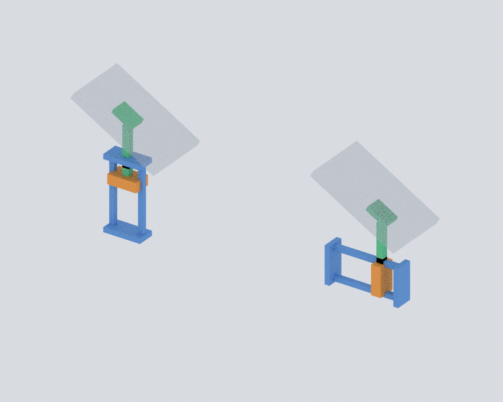
Project the actual displacement, not the stroke label
For carriage displacement d and unit contact normal n, useful normal approach is the dot product d · n. A stroke number alone says nothing about that projection until the guide direction and normal share a frame.
The recovered +Z guide gave about 0.866 mm of normal approach per millimetre of slide travel. The +X guide gave 0.500 mm per millimetre. Those ratios explain why identical 18 mm travels led to different face relations.
Dividing the initial 12 mm gap by each ratio gives a model-derived closure travel of about 13.856 mm for the parallel slide and 24.000 mm for the perpendicular slide. These values come from the measured static geometry and declared plane model. We did not move a contact point continuously through those positions, measure the first physical touch or execute a compliant stroke.
Finite faces checked the scalar projection
A dot product can be misleading if the tool face slides past the plate. We therefore checked the actual finite head and plate faces, not infinite planes alone. The guide axis came from the evaluated inner cap-face centres. The spindle axis, head normal and plate normal were reconstructed independently from finite vertices.
At all six samples, every projected head-face corner remained inside the corresponding plate face with at least about 30 mm of margin. That made the positive signed gaps equal to the measured Euclidean solid distances in the separated poses. At the parallel 18 mm pose, a full separating-axis check instead found positive-volume overlap, so the finite distance was zero.
Our scene contained 18 closed meshes, and we captured all their evaluated vertices at each of the six static poses. An independent calculation checked each head against its own plate and reproduced the guide travel, normal projection and finite relation. Captured corners were checked against authored geometry within 4 micrometres; distance and classification comparisons allowed 8 micrometres. These are digital consistency bounds, not manufacturing tolerance or hardware accuracy.
The rail, carriage and tool junctions were schematic. Their internal clearances and load-bearing connections were not validated by the head-versus-plate comparison.
Vendor examples define the direction vocabulary
PushCorp’s current compliance-device overview distinguishes travel parallel to a spindle from travel perpendicular to it. It gives flap-disc and dual-action examples for the parallel arrangement, and bristle-brush and saw examples for the perpendicular arrangement. The page also distinguishes active closed-feedback devices from passive devices whose force is set with external air regulation. See the PushCorp overview.
Those are vendor application examples, not universal media recommendations, and they do not validate our generic geometry. The broader robot actuator guide helps separate actuator families. Our impedance-versus-admittance guide addresses how compliant behavior can be controlled. This experiment answers an earlier question: whether the permitted mechanical direction can supply the required normal travel at all.
Choose the mechanism direction before tuning force
Start by writing the spindle axis, guide direction and required contact normal in one frame. Recover the carriage’s actual displacement from the mechanism, project it onto the normal, and then confirm that the finite faces still overlap laterally. Keep signed plane gap, Euclidean separation and solid overlap as separate quantities.
For this authored setup, the parallel +Z slide had enough geometric normal travel within 18 mm; the perpendicular +X slide did not. That conclusion is local to the declared normal and face geometry. A different surface orientation can reverse the choice.
The experiment did not measure stiffness, regulated force, air pressure, feedback accuracy, contact response, machining quality, wear, continuous motion, robot operation, hardware performance or safety. Those checks come after the mechanism can reach in the required direction.