In my actual AI-operated Blender 5.2.2 LTS experiment, the same 30.00 mm horizontal input produced 5.29 mm of rise on a 10° ramp and 13.99 mm on a 25° ramp. Both complete follower-shoe footprints remained strictly inside their finite ramp faces. The surprise was at the high end: the 10° case retained only 0.23 mm of longitudinal edge margin, while the 25° case retained 1.55 mm. A steeper ramp created more lift and more remaining end margin in this particular setup because the fixed 30 mm shoe was parallel to the ramp, so its horizontal projection became shorter as the angle increased.
That result is why I would not choose a wedge from input × tan(angle) alone. The useful geometry decision needs two measurements at once: the vertical rise and the smallest signed margin from the shoe’s full lower face to every finite ramp edge. A center point can lie on the inclined plane even after a corner has left the available surface.
The same input produced two different rises
An inclined plane converts horizontal displacement into vertical displacement. The OpenStax discussion of simple machines, checked October 9, 2026 KST, supplies the inclined-plane and wedge terminology and the familiar length-height context. I used that source only for the geometric concept. It does not validate my dimensions, force, efficiency, friction, self-locking behavior, or hardware suitability.
Cell X has the same direction as Blender world X. I removed each cell’s 200 mm X or 140 mm Z layout offset before comparing positions. Those offsets arranged the examples; they were not input travel or rise.
I authored two ramp angles, 10° and 25°, and two input positions, 0 and 30 mm. Each combination was a separate static Blender cell. The 70 mm-long ramp moved 30 mm in negative cell X for the shifted condition. The shoe’s lower-face center stayed at cell X = 25 mm, so the point beneath it moved from local ramp X = 25 mm to local ramp X = 55 mm.
The measured input was 30.00 mm in both angle pairs. The actual shoe-center rise was 5.29 mm at 10° and 13.99 mm at 25°. Those values agree with the expected direction of the nominal calculation 30 × tan(angle), but the calculation was only a cross-check. The reported values came from evaluated finite mesh coordinates after the separate cells’ display translations were removed.
This was not a moving wedge test. Blender did not solve contact or make the shoe follow the ramp. I independently authored four poses, then recovered the ramp planes and shoe faces from the resulting geometry. The experiment demonstrates the geometry of those four states, not a continuous trajectory between them.
Four closed-solid cells kept the comparison controlled
Each cell contained one closed trapezoidal ramp prism and one closed rectangular shoe. Across the four cells, the experiment used eight unshared meshes, 64 world-space vertices, and 96 native triangles. Three complete geometry readbacks and a different representative read of the 25°/30 mm cell confirmed that the measured objects were the ones actually created.
The ramp was 70 mm long in local X and 40 mm wide in Y. Its bottom sat 10 mm below the local reference, while its top followed the selected slope. The shoe’s lower face was 30 mm along the ramp tangent and 20 mm across Y. The shoe body was 8 mm thick along the ramp normal. Those dimensions are generic authored inputs, not a vendor model.
Keeping the lower-face center at cell X = 25 mm was essential. It made the ramp translation the input while the shoe position encoded the resulting height at the new local ramp coordinate. It also exposed the finite-end question: the shoe was not a point, and half of its 30 mm tangent length extended on either side of that center.
The actual slope recovery was approximately 10° or 25° as authored. Every ramp top and every shoe lower face remained within the declared numerical seating band. That classification means the measured vertices were consistent with the same supporting plane within the calculation allowance. It does not mean Blender found physical contact, contact pressure, or equilibrium.
The coordinate and comparison allowances were 4 and 8 micrometres. They bounded numerical consistency among independently recovered coordinates and classifications. They are not machining tolerances, surface accuracy, sensor precision, or recommended mechanical clearance.
Full-face support changed the interpretation
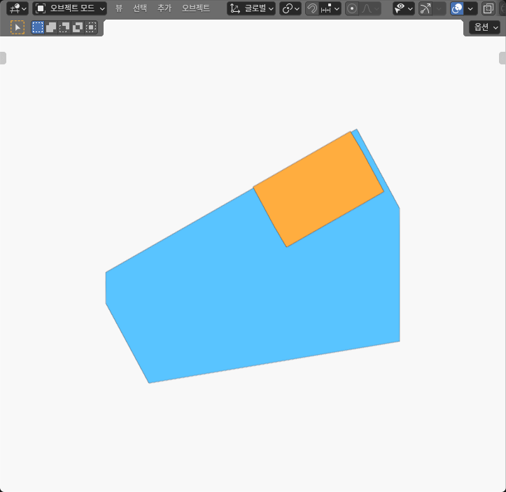
A single witness point would have missed the most useful part of this experiment. I reconstructed the ramp top as a finite plane and projected all four lower shoe corners into tangent and transverse coordinates on that plane. I then measured signed margins to the low end, high end, negative-Y edge, and positive-Y edge.
All four projected footprints were strictly inside their ramp boundaries. At zero input, both angles had a minimum edge margin of 10.00 mm. The controlling boundaries were the two Y-side edges: the ramp was 40 mm wide and the shoe was 20 mm wide, so the centered footprint left 10 mm per side.
After the 30 mm ramp shift, the limiting boundary changed to the right longitudinal edge. The 10° shoe retained 0.23 mm, while the 25° shoe retained 1.55 mm. Both results were positive, but they describe very different reserves. Rounding a center coordinate or checking only plane coincidence would not reveal that difference.
The larger 25° margin initially seems counterintuitive. It would be easy to repeat the generic claim that a steeper ramp always consumes finite surface faster. That is not what this controlled geometry did. The shoe length was fixed along the ramp tangent. Its horizontal half-length was 15 × cos(angle), so the 25° shoe projected less distance toward the finite X end than the 10° shoe. With the same cell-X center and same 30 mm ramp shift, that shorter horizontal projection left more end room.
The margin is easiest to understand by separating the two coordinate systems. In cell X, the lower-face center stayed at 25 mm while the shifted ramp’s usable X interval ended at 40 mm. That left 15 mm from the center to the end before accounting for the shoe. The shoe then consumed 15 × cos(angle) of that cell-X reserve. At 10°, this horizontal half-projection was nearly the whole 15 mm, leaving only a narrow strip. At 25°, the half-projection was shorter. Converting the remaining cell-X strip back to distance along the inclined face produced the measured 0.23 mm and 1.55 mm margins. This decomposition is a check on the measured polygons, not a substitute for them.
This result is specific to the frozen geometry. Changing how the shoe length is defined, fixing a different datum, rotating the shoe differently, or comparing equal travel along the ramp rather than equal horizontal input could reverse the margin ordering. The practical lesson is to model the actual follower face and actual input definition instead of attaching a universal clearance conclusion to the angle alone.
The measured table keeps rise and margin together
The zero-input rows establish each angle’s baseline height and footprint. The shifted rows report paired rise from that baseline. “Numerical seating band” means the four lower corners and ramp plane agreed within the calculation band; it is not a physical contact statement.
For each pair, I recovered the finite X-cap positions of the ramp rather than trusting an object origin. Their change gave the input. I recovered the shoe-body center from all eight corners and compared it with the matching zero-input cell after removing the authored display offset. That difference gave the rise. I also checked the four-corner lower-face center’s rise against the body-center result within the numerical comparison band. Finally, I projected every lower corner onto the measured ramp basis and compared it with all four top-face boundaries. The result therefore joins three independent questions—input, output, and footprint—without allowing one nominal label to stand in for another.
| Ramp angle | Horizontal input | Measured rise | Limiting signed edge margin | Finite-footprint result |
|---|---|---|---|---|
| 10° | 0.00 mm | 0.00 mm | 10.00 mm, Y sides | Strictly inside; numerical seating band |
| 10° | 30.00 mm | 5.29 mm | 0.23 mm, right longitudinal edge | Strictly inside; numerical seating band |
| 25° | 0.00 mm | 0.00 mm | 10.00 mm, Y sides | Strictly inside; numerical seating band |
| 25° | 30.00 mm | 13.99 mm | 1.55 mm, right longitudinal edge | Strictly inside; numerical seating band |
The table should not be read as a design approval. A 0.23 mm geometric margin may be unacceptable once manufacturing variation, guide play, compliance, thermal change, debris, or surface error is introduced. The experiment did not model any of those effects. It shows the nominal finite reserve that a later tolerance analysis would have to consume.
The result also differs from the tool-side compliance slide-direction experiment. That work compared how equal slide strokes project onto an oblique contact normal. Here the input translated a finite ramp, and the output combined lift with the containment of a complete parallel shoe. It also differs from the flat-faced cam follower width experiment, where follower width changed support on a faceted cam. In this experiment, shoe dimensions stayed fixed while angle and ramp translation changed.
Static geometric seating is not a working wedge
The four cells were prescribed static arrangements. There was no gravity, guide, spring, actuator, collision response, friction coefficient, or force balance. The word “input” labels a measured 30 mm ramp translation, not a controller command or a powered stroke.
Likewise, the numerical seating-band result is weaker than physical contact. It says the shoe’s lower face and ramp top were geometrically coincident within the arithmetic allowance. It does not prove positive pressure, distributed load, stability, or that a real shoe would remain seated. A guide or other constraint would be needed to impose that relationship in hardware.
The experiment did not test force multiplication, efficiency, back-driving, or self-locking. It did not estimate friction, pressure, stress, wear, deformation, or damage. It did not measure a maximum stroke. The two input samples at each angle do not certify every intermediate position, and they do not exclude interference with a frame that was not modeled.
The top face was finite even though its plane equation extends infinitely. That distinction is central. The plane can return a valid height at a point beyond the solid’s end, but the mechanism would no longer have a ramp surface there. This is why a height equation and a finite-footprint test must remain separate checks.
The generic solids also omit details that often control a real wedge assembly: guide rails, end stops, fasteners, chamfers, lubrication, surface finish, surrounding structure, and tolerance stacks. None of the measured numbers should be transferred to commercial hardware without rebuilding the relevant geometry and requirements.
Use one requirement for lift and another for containment
A practical specification should state both conditions. One requirement can set the minimum vertical rise over the chosen horizontal input. A second can require every lower-face corner to retain a positive boundary margin at each checked position. The acceptable margin must come from the application’s tolerance, load, wear, and contamination analysis; this experiment does not choose it.
The repeatable workflow is compact. Model the ramp as a finite solid. Model the full shoe at its real tangent length and transverse width. Author start and end cells with the input definition held constant. Recover the actual top plane and lower-face corners. Measure paired rise, all-corner plane agreement, and four signed edge margins. Report the controlling edge rather than only a pass/fail label.
If lift is insufficient, increasing angle is one possible change. If end margin is insufficient, possible changes include lengthening the ramp, shortening the shoe, moving the starting datum, or reducing input. Those changes are not interchangeable: each changes a different part of the geometry and should be rerun through the same finite check.
For this authored model, the 25° ramp was better on both measured outputs at 30 mm input: 13.99 mm of rise and 1.55 mm of limiting margin, compared with 5.29 mm and 0.23 mm at 10°. That is a finding about these dimensions and datums, not a rule that the steeper wedge is always superior. The durable reader decision is simpler: do not accept lift until the complete follower face also fits on the finite ramp.