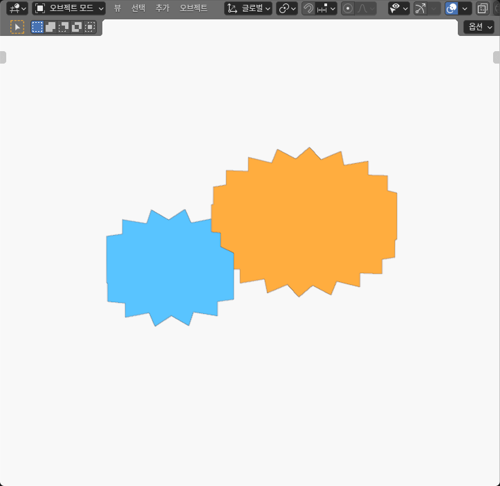
In my AI-operated Blender 5.2.2 LTS experiment, two generic gear-shaped solids kept the same authored nominal in-plane layout while I changed only their axial offset. Each solid had a measured face width of about 12 mm. At 0 mm offset, their finite axial intervals shared 12 mm. At 6 mm, the common span fell to 6 mm. At 12 mm, the end planes landed in the numerical boundary band. At 14 mm, the envelopes were separated by 2 mm.
That sequence gives a direct design warning. A 2D arrangement can remain unchanged while axial retention, a spacer stack, or a shaft shoulder moves one member far enough to halve or eliminate the available common width. The experiment did not establish a working gear mesh. It measured a necessary three-dimensional envelope condition that a planar layout leaves out.
Face width belongs in the assembly model
The selected KHK face-width page defines face width as the axial length of a gear tooth and identifies the engaged portion when a mating member is narrower. I use only that terminology. The page does not supply the geometry, offsets, acceptance threshold, or outcome for this experiment, and I do not transfer its strength discussion or any product guidance.
My two solids were intentionally generic. One outline alternated root and tip radii around 12 nominal teeth; the other did the same around 18. Their authored nominal pitch references were 12 and 18 mm, and their in-plane centre spacing was 30 mm. Those values positioned the shapes for a controlled comparison. The meshes did not contain true pitch circles or involute tooth flanks, and Blender did not solve gear contact.
Both solids were 12 mm wide along the common Z direction. Four independent static cells used relative axial offsets of 0, 6, 12, and 14 mm. Their X-Y outlines and orientations stayed unchanged after the separate display placements were removed. This isolated the question I wanted to answer: how much finite axial span remained common to the two complete envelopes?
That common span is necessary evidence, but it is not a performance rating. A positive number means the finite axial intervals overlap. It does not establish conjugate tooth contact, contact ratio, backlash, load sharing, stiffness, wear, noise, lubrication, or torque capacity.
I measured the finite cap planes
I did not use object origins or trust the nominal 12 mm labels. For each solid, the evaluated lower and upper cap vertices defined two finite axial planes. Their cap means recovered the extrusion axis, and the complete vertex set checked that the body stayed between those planes.
The interval calculation is plain. For intervals with lower and upper endpoints, the common span is the smaller upper endpoint minus the larger lower endpoint, clamped at zero. If that signed value is negative, its magnitude is the axial separation. This makes the controlling faces explicit: one member’s upper face and the other’s lower face determine what remains.
I also checked the in-plane arrangement separately. The recovered centre spacing rounded to 30.00 mm in every cell, and the complete outlines corresponded after only the prescribed axial translation was removed. That does not make the 30 mm layout a valid mesh. It shows that the changing overlap came from the isolated Z offset rather than an unintended X-Y shift.
The coordinate and comparison bands in this model distinguish numerical agreement from a strict separation or positive common span. They are bookkeeping for the finite data, not machining tolerances. In particular, a near-zero interval result cannot be promoted to physical contact merely because it rounds to 0.00 mm.
The measured sequence was 12, 6, boundary, gap
The actual finite cap intervals produced the expected progression, but the interpretation matters more than the arithmetic.
| Axial offset | Measured common span | Measured axial gap | Finite interval classification | Reader meaning |
|---|---|---|---|---|
| 0 mm | 12.00 mm | 0.00 mm | Positive common span | Both measured face-width intervals coincide axially |
| 6 mm | 6.00 mm | 0.00 mm | Positive common span | Half of the measured width remains common |
| 12 mm | 0.00 mm | 0.00 mm | Numerical end-plane boundary | Do not call this physical contact or usable engagement |
| 14 mm | 0.00 mm | 2.00 mm | Strict axial envelope separation | The complete finite axial intervals no longer overlap |
At zero offset, the two 12 mm intervals coincided, so the common span was the full measured width. Moving one solid 6 mm left 6 mm in common. This is the useful partial-overlap case: the in-plane layout did not change, yet the available axial envelope was cut in half.
The 12 mm case is a boundary case, not a successful zero-clearance fit. The independently reconstructed cap planes met within the declared numerical band. The static model contains no material deformation or contact response that could decide whether a manufactured pair would have clearance, interference, or load-bearing contact.
At 14 mm offset, the interval relation became unambiguous: there was no common span and the nearest axial end planes were 2 mm apart. This is enough to reject that state as having finite axial face overlap. It is still not a demonstration of gears disengaging through rotation, because the cell is one authored static placement.
Turn the result into an axial-retention decision
The practical use is to add an axial budget alongside the familiar in-plane layout. Start with each member’s measured or specified face interval in a common shaft frame. Then include the locations established by bearings, shoulders, spacers, retaining rings, hubs, and housing datums. Evaluate the common span at every relevant stack extreme rather than only at the nominal assembly.
A useful worksheet can remain small:
- Record both lower and upper face positions from one declared axial datum.
- Compute the signed common span from the two finite intervals.
- Keep the controlling face pair with the result so a shoulder or spacer change can be traced.
- Compare the remaining span with a separately justified requirement for the real transmission.
- Run the contact, backlash, deflection, lubrication, and strength analyses as separate checks.
The fourth step is deliberately external to this experiment. Nothing here determines how much common width is sufficient. A real minimum depends on tooth geometry, load distribution, shaft and housing deflection, manufacturing tolerances, thermal movement, bearing endplay, and the application’s acceptance criteria.
The result can still guide a concrete edit. If the nominal assembly leaves too little common span, move a shaft shoulder, change a spacer, revise hub placement, improve axial retention, or reconsider face widths. Then recalculate the complete interval stack. Increasing face width may help the axial envelope, but it does not by itself validate the tooth geometry or the rest of the transmission.
It is equally important to preserve direction and datum. Reporting only “6 mm offset” hides which gear moved and which face became controlling. A reviewable assembly record should name the fixed datum, both face intervals, the relative offset, and the resulting common span or gap.
This is separate from centre distance and bevel apex
The earlier spur-gear centre-distance experiment covers the in-plane centre-distance and contact-ratio questions. Here the authored nominal in-plane layout remains unchanged. The measured variable is axial common span between finite face intervals.
The bevel-gear apex experiment asks whether perpendicular reference axes and cone generators share an apex. This experiment has parallel axes, no cones, and no extended-line construction. Its controlling evidence comes from finite end planes along one common axial direction.
Those distinctions make the result more than another generic clearance example. The relevant action is not to move centres until two silhouettes touch. It is to manage axial locations so a separately required common face span survives the assembly stack.
The same distinction also helps during CAD review. A top or side view may show the intended centre spacing and apparent tooth interleaving while hiding axial withdrawal. A section, interval report, or measured face-position table is needed to reveal the omitted dimension.
What this static experiment does not establish
This was an authored virtual geometry experiment, not a physical gear test. The four cells were independent static poses. I did not rotate the solids, solve collision or contact, model shafts and bearings, or measure forces, torque, efficiency, wear, vibration, heat, noise, or safety. The pointy polygon prisms are not vendor CAD and should not be used for tooth manufacture.
The result is intentionally narrow: at the measured states, the finite axial envelope changed from 12 mm common span to 6 mm, then to an unresolved numerical boundary, and finally to a strict 2 mm gap. That evidence is enough to show why spacer, shoulder, and retention choices belong in a three-dimensional gear layout review. It is not enough to declare any positive span acceptable or any pair a functioning gear mesh.
For a real design, preserve the necessary-versus-sufficient distinction. First require positive common axial span under the full assembly stack. Then justify how much span is required and verify the actual tooth geometry and operating conditions. A clean 2D arrangement is one input to that process, not its conclusion.