Two shaft directions can be perpendicular and still fail the basic pitch-cone placement check. In my Blender comparison, all three cone pairs had an axis angle of approximately 90 degrees. Only the matched pair shared an apex; its selected finite generator edges corresponded within the model’s numerical band. Moving one cone’s apex 5 mm along its own axis preserved the 90-degree direction test but left the actual apices and finite axis segments 5 mm apart. Moving it 5 mm sideways made even the mathematically extended axes miss by 5 mm.
The useful diagnostic is therefore not “Are the axes at right angles?” It is a sequence: compare direction, compare actual apex position, check the finite axis domains, and then check the finite pitch-cone generators relevant to the intended pair. Each question can fail independently.
I built three generic static cone pairs in an AI-operated Blender 5.2.2 LTS session on October 8, 2026. The cones are 32-facet closed reference solids with a 20 mm base radius and 20 mm axial height. They are pitch-reference shapes, not gear teeth or vendor models. No rotation, rolling, tooth contact, torque, or physical mounting was simulated.
A right angle checks direction, not location
The first pair used a common apex. Cone A’s recovered axis pointed approximately along world Z and cone B’s along world X. Their recovered direction angle was approximately 90 degrees. Their apex separation, finite-axis distance, extended-axis distance, and selected-generator distance all measured 0 mm within the model’s comparison contract.
For the second pair, cone B was shifted 5 mm along world X, which is its own axis direction. The direction vectors did not change, so the angle remained approximately 90 degrees. The apex moved, however. Its separation from cone A’s apex became 5 mm, and the two finite axis segments were also 5 mm apart.
The third pair shifted cone B 5 mm along world Y, perpendicular to both axis directions. Again the directions stayed approximately perpendicular. This time the two axes occupied different parallel planes. Apex separation, finite-axis distance, and extended-line distance were all 5 mm.
This distinction matters before any tooth analysis. Axis direction describes orientation. A common apex is a positional condition. Meeting one does not imply the other.
Three checks separated the failure modes
| Case | Direction angle | Apex / finite-axis distance | Extended-axis distance | Selected generator distance |
|---|---|---|---|---|
| Matched | ≈90° | 0 / 0 mm | 0 mm | 0 mm; whole selected edge corresponded within 8 µm |
| Axial shift +5 mm X | ≈90° | 5 / 5 mm | ≈0 mm, outside cone B’s finite axis domain | 3.54 mm |
| Skew shift +5 mm Y | ≈90° | 5 / 5 mm | 5 mm | 5 mm |
The axial-shift row is the useful trap. If I replaced each finite axis with an infinite mathematical line, the two lines still intersected near zero distance. That intersection lay outside cone B’s finite axis segment. The actual apex and the finite segment remained 5 mm from cone A’s axis reference. An extended-line result alone would have hidden the placement error.
The selected finite generator edges told the same story with more geometric detail. In the matched pair, generator A at base index 1 and generator B at base index 17 followed the same parameterized edge within the 8-micrometre correspondence band. In the axial-shift pair, their closest distance was about 3.54 mm. In the sideways-skew pair, it was 5 mm.
Those edge labels do not claim tooth contact or a working contact line. They identify one prescribed pair of finite cone edges. No conclusion is made about every possible surface point or an unmodeled tooth flank.
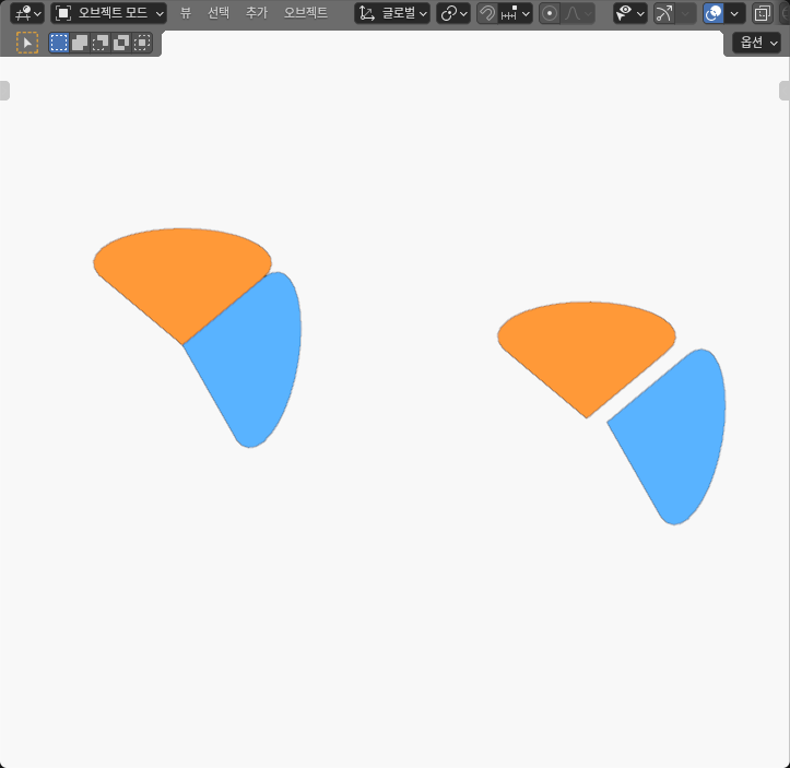
Finite axis segments prevent an infinite-line false pass
An axis recovered from a finite cone has a natural domain: from its apex toward the centroid of its 32-point base ring. That finite segment is different from an infinite line carrying the same direction. The distinction is easy to lose when a CAD or math tool reports only direction vectors and closest points on unbounded lines.
For the matched pair, finite and extended checks agree. Both actual apex vertices occupy the same point, the finite axis segments meet there, and the selected generator edges correspond across their whole length within the numerical band.
For the axial shift, the extended lines also meet, but the meeting point requires continuing cone B’s reference backward past its actual apex. The finite axis check rejects that extrapolation. The 5 mm apex error is real in the authored geometry even though the unbounded line distance is effectively zero.
For the skew shift, extending the axes cannot rescue the pair. One line lies in a plane offset 5 mm in Y from the other, so their shortest distance stays 5 mm. This is a different failure from the axial case and suggests a different correction: lateral placement rather than an along-axis translation.
The numeric bands in this experiment are controls for digital geometry. The common-apex and full-generator comparison used an 8-micrometre band, and reported distances reserve a small arithmetic margin. These are not mounting tolerances, metrology accuracy, or manufacturing recommendations.
Pitch-cone language does not prove tooth meshing
KHK’s bevel-gear dimension reference was checked on October 8, 2026 and describes bevel-gear pitch surfaces as cones, relates a pair through intersecting axes and shaft angle, and discusses the reference contact line. That source provides the terminology for asking whether a cone pair shares the intended geometric construction. It does not validate my generic cones, dimensions, or placements.
The experiment contains no teeth. It therefore cannot test tooth thickness, backlash, contact ratio, tip or root clearance, rolling action, or load distribution. A common apex is a prerequisite in the idealized reference construction used here, not a complete gear-design approval.
This separates the question from the spur-gear center-distance experiment. That study uses actual involute tooth geometry to examine spacing, overlap, and active contact. The present experiment stops earlier: it checks whether two generic finite pitch references are placed around one common apex.
It also differs from the gearbox backlash history experiment. Backlash there is a stateful angle-history problem. These cone pairs are independent static layouts with no approach history, tooth clearance, or rotation transfer.
The Blender method recovered geometry instead of trusting origins
I kept the three pairs as independent static layouts and checked their complete captured geometry repeatedly. These were repeated digital readbacks, rather than physical trials or a motion simulation.
For each cone, the actual axis came from the captured apex and the centroid of the actual base ring. I did not use the object origin as a substitute. The angle came from the recovered axis vectors. The apex distance came directly from the recovered apex vertices.
The finite-axis distance used constrained segment-to-segment minimization. The extended-axis distance used the same recovered directions without segment bounds. The generator check used the actual apex-to-base edges selected in the frozen input. A second calculation independently reconstructed those world-space segments and agreed with the audited results.
The matched selected edges were checked along the same parameter, not only at one endpoint. Saying they correspond within 8 micrometres is more accurate than calling them mathematically identical. Finite floating-point coordinates remain finite, and correspondence of one edge pair does not prove full-surface contact.
The three cells are separated by 100 mm in the editor for display. That spacing is not a shaft center distance, housing dimension, or real assembly layout. The cones themselves remain generic 20 mm radius by 20 mm height reference shapes.
What this experiment cannot establish
The cone models do not include shafts, bearings, housings, fasteners, keys, gear teeth, or a mounting datum. They cannot show whether a physical assembly holds the axes at the intended angle or position under load. They do not measure manufacturing error or acceptable apex offset.
No contact solver ran. The experiment did not rotate either cone, establish conjugate motion, calculate ratio, or find a physical contact pattern. It did not evaluate material, torque, strength, wear, noise, efficiency, lubrication, or safety.
The selected generator pair is a diagnostic reference, not proof that those edges would be a physical line of tooth contact. In the shifted cases, its distance reports the chosen finite edges only. Another untested surface pair could have a different distance, and no absence-of-interference claim follows from these numbers.
The static samples also do not establish a tolerance. A 5 mm shift was selected because it makes the three failure modes clear. The 8-micrometre correspondence band checks numerical reconstruction; it does not suggest that a real bevel-gear mounting may use that tolerance.
Check the apex before tuning anything downstream
For a practical reference-geometry review, I would preserve four separate fields for each cone: actual axis direction, actual apex point, finite axis interval, and the finite generator or surface feature being compared. Then I would check them in that order.
If the directions are wrong, correct orientation first. If directions are right but the apices differ, inspect translation. If extended axes meet while finite axes do not, find whether the intersection lies beyond an actual apex, as it did in the axial-shift case. If the apex and finite axes pass, compare the chosen finite generators before moving on to teeth.
Only after those reference checks would tooth geometry, backlash, contact, and load analysis become meaningful. Adjusting downstream tooth parameters cannot repair a cone pair whose reference geometry is positioned around different apices.
The direct result from these three Blender cells is concise: all three axis pairs were approximately perpendicular, but only one pair had a common actual apex and corresponding selected generator. The axial shift passed an infinite-line intersection check while failing the finite geometry. Perpendicular direction was necessary for this 90-degree layout, but it was not enough.