A replacement roll can have journals that clear both end openings while its barrel intersects the neighboring rolls. That was the failure exposed by Physical AI Lab’s AI-assisted Blender 5.2.2 LTS experiment: increasing the barrel diameter from 16 to 24 mm left about 8 mm of clearance at the journal openings, yet produced two solid intersections inside the receiving pocket. Increasing the neighboring-roll center spacing from 38 to 46 mm removed those intersections in the tested static placement. The useful assembly check is therefore the relationship between the whole roll and its receiving space, not just whether the shaft ends fit.
These are deliberately small, generic dimensions for a virtual geometry study. They are not dimensions of a production rolling mill, measurements from a factory, or evidence that a robot can execute a roll change.
Why I separated the barrel check from the journal check
Fives’ official Roll Change Robot description, checked on October 9, 2026, describes handling work and backup rolls, adapting to dimensions, and considering the combination of roll diameters. That provided the industrial motivation for this experiment. The page supplied neither the CAD geometry nor the dimensions used here; I did not test the commercial robot or its retrieval head.
A journal is the narrower section at either end of a roll. It can clear an opening even when the wider working barrel does not clear the surrounding equipment. I made that distinction explicit by building two functional groups: a candidate roll and a receiving pocket. The candidate roll contained a barrel and two journals. The pocket contained two neighboring-roll envelopes and two square end collars, each collar built from four closed frame members.
The three roll members overlapped internally to form one connected geometric group. The ten receiving members also formed a connected group. These internal overlaps represented the grouping of the model; the assembly question concerned intersections between the two groups. I kept all solids intact and checked every roll-to-pocket pair, rather than deleting an obstructing surface to make the placement look successful.
Four placements made the diameter mismatch visible in the data
The shared design axis was X, and the moving roll translated only along X. The barrel extended from −30 to +30 mm. The two journals extended from −40 to −26 mm and from +26 to +40 mm, respectively. Each journal therefore overlapped the barrel by 4 mm. The small barrel and journals had nominal radii of 8 and 3 mm; the larger version used 12 and 5 mm.
The receiving neighbors had nominal radii of 10 mm and extended from X = −36 to +36 mm. Their centers initially sat at Y = −19 and +19 mm. The end collars occupied X = −37 to −35 mm and +35 to +37 mm, with 26 mm square openings and 70 mm square outer envelopes. Curved profiles were closed 32-sided prisms, not analytic cylinders.
I constructed four independent static cells. The first placed the small roll 80 mm outside the pocket along negative X. The second placed it at X = 0. The third put the larger roll at the same X = 0 position without changing the receiving pocket. The fourth kept the larger roll but moved the neighboring centers to Y = −23 and +23 mm. The collar geometry remained unchanged.
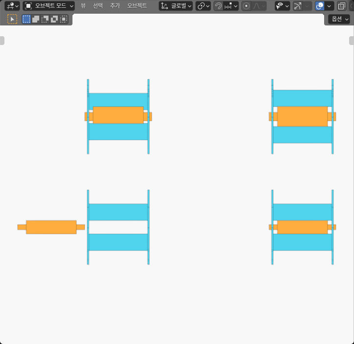
The image is an original opaque SOLID editor capture. The 220 mm horizontal and 140 mm vertical cell offsets only separate the examples on screen; they are not stages of a simulated loading trajectory. No surfaces were hidden, cut away, or made transparent for the image.
| Static state | Barrel diameter | Neighbor center spacing | Finite solid result | Assembly reading |
|---|---|---|---|---|
| Small roll outside, X = −80 mm | 16 mm | 38 mm | All 30 cross-group pairs disjoint | An outside placement is not a tested insertion path |
| Small roll inside, X = 0 | 16 mm | 38 mm | All 30 pairs disjoint; closest-distance bound about 0.995–1.000 mm | Both journal openings and the barrel envelope clear in this placement |
| Large roll, original pocket, X = 0 | 24 mm | 38 mm | Two barrel/neighbor pairs have strict interior intersections; 28 pairs disjoint | Clear journals do not make the larger barrel fit |
| Large roll, wider pocket, X = 0 | 24 mm | 46 mm | All 30 pairs disjoint; closest-distance bound about 0.995–1.000 mm | Changing neighboring-roll spacing resolves this static diameter mismatch |
The passing journals were the misleading result
At X = 0, both journals covered the full 2 mm axial thickness of their matching collars. The small journals remained about 10 mm from each of the four finite inner collar faces. The large journals remained about 8 mm away. Those checks passed for the larger roll in both receiving configurations, including the one with barrel interference.
The barrel-to-neighbor cardinal projection explained the failure: half the original center spacing was 19 mm, while the larger barrel and neighbor radii summed to 22 mm. That gave a signed transverse gap of approximately −3 mm on each side. I treated this as a diagnostic projection. The actual intersection verdict came from the full finite solids and verified interior points, not from the negative projection alone.
With 46 mm between neighboring centers, the corresponding half-spacing became 23 mm. The signed cardinal gap became approximately +1 mm. All 30 finite pairs were then disjoint. The independently calculated closest-distance bounds were approximately 0.995 to 1.000 mm for both the small inserted roll and the larger matched roll; the small range reflects finite faceted geometry and outward numerical bounds, not a manufacturing tolerance.
The end frames needed a separate axial check. At X = 0 the barrel ended 5 mm before either collar, even though its cross section projected into the opening. Conversely, in the outside cell, the nearest journal tip was 3 mm before the entrance plane. That 3 mm was only an X-plane offset; it was not the full three-dimensional distance to a finite frame face.
What I would check before approving the next assembly stage
This experiment changed the order of the checks I would use for a roll-loading model. I would first bind the candidate barrel and journal dimensions to the actual receiving configuration. I would then check both full journal spans against the finite end openings, and check the entire barrel against neighboring rolls and frame members. Only after a static placement passes would I investigate the swept insertion route and the equipment states along that route.
Increasing neighbor spacing solved the illustrated geometric problem, but it is not an operating recommendation for a real mill. Actual roll spacing can be constrained by the process, support structure, and machine design. A configuration that is impossible to change should reject the mismatched candidate rather than inherit the result from a smaller roll.
For the next question—whether a valid end placement can actually be reached—the dovetail assembly access experiment separates cross-sectional fit from a finite loading route. The bayonet coupling assembly experiment adds another distinction: an acceptable insertion state and an acceptable retained state require different geometric checks.
What the Blender experiment establishes
I directly created and read back 52 closed meshes across the four cells: 1,536 evaluated world-space vertices and 2,864 native triangles. Three complete readbacks, a separate representative capture, and an independent coordinate analysis checked the authored dimensions, connected groups, all 120 cross-group pair relationships, and finite journal openings. Forty deliberately corrupted copies of the actual evidence were rejected by the analysis checks. These are checks on the virtual geometry and its evidence, not tests of physical equipment.
I did not animate or certify a continuous insertion path, run contact or rigid-body dynamics, measure force, attach bearings, or execute a robot controller. The generous collar openings represent clearance envelopes rather than a seated bearing assembly. Friction, deflection, thermal growth, tolerances, grip stability, load capacity, and safety remain outside this study. Its supported finding is narrower and useful: journal clearance can pass while barrel interference fails, so both must be checked against the same finite receiving configuration.