The insert fit the seated dovetail without touching either retaining rail, yet the same rigid insert could not pass straight down through the throat. In my Blender comparison, the top-loading throat pose intersected each rail by 645.239 mm³. An end-loading pose partially inside the receiver remained separate from both rails by about 0.525 mm and from the floor by 1.000 mm. That makes an open receiver end the next assembly route to check. If top loading is mandatory, the retaining geometry needs a change.
This was an AI-operated Blender 5.2.2 LTS experiment with six independently authored static translations, 24 unshared closed meshes, and 192 evaluated vertices. It did not animate an assembly or prove a physical dovetail can be assembled or retained safely.
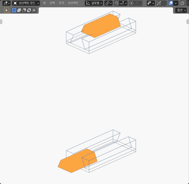
A seated fit does not define an assembly route
The receiver was deliberately modeled as three finite solids: a floor and two sloped retaining rails. It was not replaced by a filled bounding box. Along X, all three receiver pieces extended from -0.045 m to 0.045 m, giving a 90 mm receiver length. In the YZ profile, the floor spanned Y = -0.022…0.022 m and Z = 0…0.004 m.
The left rail used the polygon (-0.022, 0.004), (-0.014, 0.004), (-0.008, 0.018), and (-0.022, 0.018) metres in YZ. The right rail mirrored it. Their upper inner endpoints left a 16 mm throat at Z = 0.018 m.
The insert extended from X = -0.025…0.025 m, so its length was 50 mm. Its YZ profile was (-0.013, 0.005), (0.013, 0.005), (0.0075, 0.017), and (-0.0075, 0.017) metres. That made its lower edge 26 mm wide and its upper edge 15 mm wide.
Those dimensions explain the central question. The 15 mm top can sit below a 16 mm throat once the wider lower section is already under the rails. But the 26 mm lower edge cannot pass straight through that throat. A correct final fit therefore says nothing by itself about whether vertical insertion is available.
The Blender 5.2 LTS Extrude Faces manual was checked on October 8, 2026. It provides the terminology for extending faces into finite geometry. I constructed these generic solids through Blender’s data API and did not claim that the documented operator, Blender, or the manual validated a physical dovetail.
Six poses separated fit from access
Each pose used the same insert and receiver geometry with identity rotation and scale. Only the authored insert translation changed. The top-loading cells moved the insert along Z by 18, 9, and 0 mm. The end-loading cells moved it along X by -75, -45, and 0 mm. I entered metre equivalents and built the profile corners through the data API. Display columns were spaced 400 mm along X, with the top row 180 mm above the lower row; I subtracted those display offsets before measuring. Neither spacing is an assembly clearance.
| Static pose | Authored insert translation | Rail relation and measured value | Floor relation | What the sample establishes |
|---|---|---|---|---|
| Top above | Z +18 mm |
Separate · 5.000 mm gap per rail | Separate · 19.000 mm | Clear pose above the throat |
| Top throat | Z +9 mm |
Intersects · 645.239 mm³ per rail | Separate · 10.000 mm | Straight top entry is blocked at this sample |
| Top seated | 0 mm |
Separate · 0.525 mm gap per rail | Separate · 1.000 mm | Final profile fits the three-piece receiver |
| End outside | X -75 mm |
Separate · 5.028 mm 3D gap per rail | Separate · 5.099 mm | Insert is beyond the receiver end, with both X and profile separation |
| End partial | X -45 mm |
Separate · 0.525 mm gap per rail | Separate · 1.000 mm | Partial axial engagement remains geometrically clear |
| End seated | 0 mm |
Separate · 0.525 mm gap per rail | Separate · 1.000 mm | Same seated geometry as the top-seated control |
The top-above sample was clear because the insert was still 5 mm above each rail and 19 mm above the floor. Moving it 9 mm downward placed the wide lower profile inside both sloped rail solids, creating the same measured intersection volume on the left and right. Moving it to the seated transform restored finite clearance because the wide base was then under the retaining faces, not passing through the narrow throat.
End loading changed a different coordinate. At X = -75 mm, the insert and receiver had a 5.000 mm finite X interval gap. The YZ profiles were also separate, so the actual 3D distances were slightly larger: 5.028 mm to each rail and 5.099 mm to the floor. This is important because “outside the end” was not mistaken for profile overlap. At X = -45 mm, the finite X intervals overlapped by 25 mm while the YZ profile retained the same 0.525 mm rail and 1.000 mm floor gaps seen at the seated position.
Finite faces prevented two common shortcuts
The first shortcut would be checking only the 16 mm throat against the 15 mm top width. That comparison ignores the 26 mm lower edge that must pass through during straight top loading. The second would be using a single receiver bounding box. A box would fill the very undercut void that makes the seated fit possible.
Instead, the independent check recovered all eight corners, six outward faces, and twelve manifold edges for each closed prism. For every insert–receiver pair, it clipped the actual convex YZ polygons and multiplied any positive profile area by the actual finite X interval intersection. When the profiles or X intervals were separate, it computed Euclidean distance using finite face and edge witnesses.
That finite calculation explains the end-outside values. A 5 mm X gap and a 0.525 mm profile gap combine to a 5.028 mm three-dimensional rail distance. The analogous 5 mm X gap and 1 mm floor-profile gap combine to 5.099 mm. Looking only at the profile would miss the real end separation; looking only at X would miss the profile contribution.
All 24 meshes and 192 vertices were checked in three independent full reads plus a distinct representative capture. The coordinate allowance was 4 μm and the two-solid comparison allowance was 8 μm. Those limits establish numerical consistency inside this experiment. They are not manufacturing accuracy, printer capability, fit tolerance, or measurement-system precision. Likewise, intersection volume is not penetration depth, assembly force, wedging, or damage.
The result supports an access decision, not a motion claim
For the authored geometry, the practical decision is to preserve access from an open receiver end. The partial and seated end samples were clear, while the sampled vertical throat pose intersected both retaining rails. A design that must accept the insert from above needs another retention concept: a removable rail, a split receiver, a tilted route demonstrated with its own finite checks, or a profile that opens sufficiently during assembly.
The six cells do not prove a continuous collision-free end path. They show three independent translations for each proposed route, not successive frames from an animation. Denser sampling would check more positions, but would still leave intervals between them. An independently audited continuous sweep would be needed to establish uninterrupted access. The experiment also omitted rail joining details, end stops, fasteners, nearby hardware, and the tool needed to place the insert.
This question differs from the tilted-peg bore experiment, which asks how angular engagement changes with bore depth. The dovetail comparison keeps one rigid orientation and tests two translation directions around an undercut. It also differs from the bin-extraction ordering experiment, which compares the order of two carried-part operations around a bin. Here the issue is local assembly access created by the receiver’s retaining profile.
The receiver is a generic three-solid envelope rather than vendor CAD or a manufactured one-piece rail. A clear static pose does not establish friction, retention, preload, stiffness, load rating, wear, backlash, print shrinkage, or safe assembly. The useful conclusion is narrower: keep an end open for this shape, or redesign the retention geometry before assuming a top-loaded assembly.
Reproduce the comparison before changing the profile
A useful rerun needs more than a picture of a trapezoid. Preserve the metre-based X ranges and YZ polygons above, build every receiver component and insert as a separate closed prism, and keep the receiver fixed in every cell. Apply only the six translations listed in the table. Then verify the evaluated vertices and transforms before computing any relation.
Use the shared seated pose as the main control: the top-seated and end-seated cells must recover the same geometry after removing display offsets. The top-above cell must remain clear, while the end-outside cell must retain both its X interval and profile gaps. Otherwise the comparison itself has changed.
Then modify one variable at a time. Widening the throat, narrowing the insert base, shortening a retaining face, or making a rail removable are candidates for a new comparison. Each changes retention geometry, and none was tested here. Measure both the revised seated clearance and the proposed entry route.
The broader lesson is to ask two questions in order: does the final cross-section fit, and can the rigid part reach that fit through the available finite opening? This experiment answered the second question differently from the first.