A double gripper has to carry the outgoing and incoming tools at the same time. Checking whether the active tool can enter the machine opening answers only half of the clearance question. The other tool, its collar and the shared wrist bridge can reach the machine face before the active tool has reached the required depth. That creates a lower limit on approach from the active tool and an upper limit from the inactive assembly.
The useful design question is whether those limits leave a common approach-depth window in both indexed configurations. A pose that works with Tool A facing forward can fail when Tool B faces forward, even though each active head fits the opening. An axial change to a collar can affect that window without changing the opening or either leading tool head.
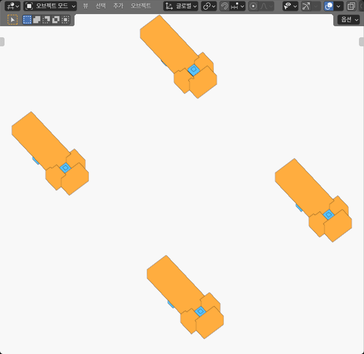
I built four complete double-gripper assemblies in Blender and read back their full geometry. In the baseline design, the A-active state met the chosen depth and clearance conditions, while the B-active state had an inactive collar overlapping the receiving wall. Moving the two collars 4 mm toward their own tool heads opened a common depth range for both indexed states. An independent finite-geometry audit and my separate checks agreed; the result concerns the modeled static assemblies, not a hardware exchange.
Keep the two carried tool identities through the exchange
KUKA’s SAACKE tool-grinder example describes picking the incoming workpiece before the door opens, removing the finished part with the other grip, and turning the wrist to load the next. The account also discusses enclosure and controller-interface work. That arrangement motivates the two-tool question here. It does not supply the geometry used below.
The official page was checked on October 12, 2026. Its publication and update dates remain unknown; the date in its URL is not treated as a publication date. I do not use a supplier CAD model, tool dimension, wrist angle, clearance tolerance or measured exchange time. The opposed rectangular tool arrangement, indexed orientations and dimensions are independently authored schematic choices.
The model has two functional cores. The moving core consists of one rigid bridge, two shafts, two wider heads and two collars. Tool A and Tool B keep their original identities. The receiver core consists of four closed wall solids surrounding a real empty rectangular opening. The wall pieces overlap at their junctions; they are not disconnected planes that merely look like a frame.
In the A-active configuration, the original Tool A points toward the opening. A proper 180-degree whole-core index about the schematic Y axis makes the original Tool B active. All seven moving members turn together. I do not relabel the forward tool as “A,” slide one tool independently to make it fit, or omit the inactive tool from the check.
Within each collar variant, the two indexed configurations use the same member geometry. The baseline and the revised collar arrangement are separate authored designs. The revision moves each collar 4 mm toward that tool’s own forward direction; the bridge, shaft and leading head dimensions stay fixed. That distinction matters when comparing a whole rigid pose with a design change.
Define insertion and clearance as separate finite conditions
The authored opening is 12 mm wide and 12 mm high. Its side-wall material extends from a front reference plane at Z = 30 mm to a rear reference plane at Z = 48 mm. Each tool head has an 8 × 8 mm rectangular cross-section. Width alone is not sufficient: the full projected shaft, head and collar footprints must fit between the complete finite inner walls.
The common approach parameter, q, translates the whole moving core along receiver +Z. For this bounded diagnostic, q lies between 0 and 30 mm. It is a coordinate in the authored model, not a measured robot command or controller position.
The active head must satisfy two axial conditions. Its leading cap must extend between 12 and 18 mm beyond the front reference plane, and the whole head must remain between the front and rear planes. Those are chosen static containment rules for this gauge. They do not prove seating, clamping, cutting or physical insertion contact.
The inactive shaft, head and collar, together with the shared bridge, must remain at least 2 mm before the front material. Every member contributes to that upper approach limit. In this layout the inactive tool sits over the left wall’s material footprint, so a forward collar can cause a real finite overlap with the wall rather than merely crossing an imaginary plane in empty space.
The 2 mm clearance is an authored diagnostic requirement. It is not a KUKA or SAACKE recommendation, a machine safety margin or an accepted hardware tolerance. The numerical correspondence and comparison guards used to inspect Blender geometry are separate from this design requirement.
Intersect the depth windows before choosing a common pose
Tool A’s leading cap is 24 mm ahead of the moving datum; Tool B’s is 20 mm ahead when that original tool faces forward. With the selected 12 mm minimum penetration, the nominal lower approach bounds are therefore q = 18 mm for A-active and q = 22 mm for B-active. The complete-head and rear-plane constraints remain part of the calculation as well.
In the baseline arrangement, the inactive collar extends 8 mm forward of the moving datum. Keeping it 2 mm before the front material gives a nominal upper bound of q = 20 mm. A-active can have a window, while B-active requires an approach deeper than that bound permits. Choosing q = 19 mm for A and q = 23 mm for B demonstrates the competing constraints at two declared static poses; it does not make the two configurations share a feasible setting.
Moving the collars 4 mm toward their own forward directions reduces the inactive forward extent after indexing to 4 mm. The bridge also reaches 4 mm ahead of the moving datum, so it now participates in the same nominal q = 24 mm upper bound. The intersection of the two indexed windows becomes the relevant quantity, rather than whichever individual pose looks most convincing.
| Authored configuration | Nominal q window | Declared sampled q | Nominal diagnostic consequence |
|---|---|---|---|
| Baseline, original A active | 18–20 mm | 19 mm | Active penetration and inactive clearance can coexist |
| Baseline, original B active | Empty: lower 22 mm, upper 20 mm | 23 mm | Adequate active depth conflicts with inactive collar clearance |
| Revised collars, original A active | 18–24 mm | 23 mm | Leaves a deeper feasible range |
| Revised collars, original B active | 22–24 mm | 23 mm | Can share the 22–24 mm range with A-active |
The table gives nominal recipe arithmetic. I separately recovered the limits from all actual captured vertices and complete finite faces. A usable interval has strict inner bounds after outward error accounting; a nominal endpoint is not automatically included.
The actual A-active baseline had a strict approach interval of approximately 18.026 < q < 19.974 mm after conservative decimal rounding. For B-active, the necessary lower depth exceeded the maximum depth allowed by the inactive assembly. Even its outward possible interval was empty, so this was a resolved incompatibility rather than an uncertain boundary case. The common baseline window was therefore empty.
With the revised collars, both indexed configurations had nonempty strict intervals. Their common interval included the conservatively rounded range 22.026 < q < 23.974 mm. The captured q = 23 mm states lay inside it. The A-active leading cap penetrated about 17 mm beyond the front plane and the B-active cap about 13 mm; the complete inactive assembly and bridge stayed about 3 mm before the front material. These figures describe the actual schematic mesh, not supplier dimensions or robot-position accuracy.
The inactive original Tool A collar in the B-active baseline had a computed finite intersection of approximately 64.000024 mm³ with the left wall. It was the only positive cross-core material overlap among the four captured states. The other three states were materially separated and satisfied the declared functional conditions. The audit computed all 220 finite member pairs and proved all 40 prescribed positive internal connections; no pair or functional boundary remained unresolved.
The geometry checks retained the fixed 4 µm coordinate, 8 µm comparison, 8 µrad angular and 20 nm arithmetic limits. The interval budget included both assemblies’ finite lever arms over the entire declared q = 0–30 mm family. My independent calculation used one additional 20 nm scalar-operation reserve and a correspondingly narrower inner window. These are computational inspection guards, not physical manufacturing or operating tolerances. Seventy deliberate corruptions of copies of the actual packets were refused; the genuine geometry was unchanged.
The interval comparison is a mathematical static envelope test. It translates the full captured rigid geometry along a declared direction; it is not an executed trajectory through intermediate positions. The intervening wrist rotation remains outside this experiment. A shared endpoint window cannot establish a collision-free rotational sweep, controller handshake, recovery sequence or cycle-time improvement.
Check the inactive collar, bridge and full machine material
A head-only check would miss the observed geometric failure in the B-active baseline. At its selected q = 23 mm, the active leading cap reaches 13 mm beyond the front plane. That sounds sufficient if the report stops at insertion depth. The original inactive Tool A collar, however, reaches Z = 31 mm against front material beginning at Z = 30 mm. The conflict belongs to an actual retained part of the carried assembly.
The bridge also needs its own check. Reducing the inactive collar’s forward extent does not remove the bridge; its top extent becomes a binding upper condition in the revised design. Repeatedly moving a collar farther back would not keep improving the window once a different full member sets the limit.
This is why I keep a separate material-pair analysis alongside the functional interval calculation. All four walls remain closed solids. All seven carried members remain present. The independent audit inspected every finite pair and proved the prescribed internal attachments make each functional core connected. A positive internal material overlap establishes connection in this authored union; it does not verify a real grip, fastener, joint strength or manufacturing method.
The functional question and material classification can disagree usefully. A tip can meet its penetration rule while an inactive collar intersects wall material. Conversely, material separation alone does not prove that the active full head lies within the chosen depth range. Each result must retain the constraint or witness that supports it.
Use the result to decide which geometry to change
For a new double-gripper layout, keep the original identities of both carried tools and write down the active and inactive roles in each indexed state. Define the finite receiving opening and front/rear references. Then derive the lower approach limit from the full active geometry and the upper limit from every inactive member and the shared carrier. Compare the intersection of both configurations before selecting a common q.
If the upper bound belongs to the inactive collar, a collar offset may be a sensible geometric variable to examine. If it belongs to the bridge, changing only the collar will stop helping. If a head fails lateral containment, changing approach depth cannot repair that lateral mismatch. An empty common interval identifies a competing constraint; it does not prescribe a safe machine redesign.
The related mould-opening article treats the clearance of a carried article and its gripper through an opening. The loaded screwdriver-envelope experiment shows why an internal tool state can change a transfer envelope. The dual pickup-head pose check considers whether two interfaces imply the same carried-object pose. Here, two simultaneously carried tool identities impose different depth and clearance constraints on one rigid exchange assembly.
Before taking a geometric window to hardware, the missing work includes actual tool and gripper geometry, machine specifications, required seating and clamping behavior, the full approach and wrist sweep, real protection clearances and controller sequencing. None of those is supplied by these four static authored states. The bounded result is whether the complete modeled parts leave a shared geometric approach window under the stated rules.