The same screwdriver housing can have two different loaded envelopes. In our Blender experiment, the retracted screw tip sat 8 mm behind the nose plane and the complete rod-plus-fastener assembly was contained in the authored cavity. In the extended state, the tip reached 18 mm beyond the nose and the full assembly was no longer contained.
This was an AI-operated static-geometry experiment in Blender 5.2.2 LTS. We compared two separate cells with identical housing, nose, guide and target geometry. We did not record a 26 mm feed motion, operate a screwdriver or test retention, tightening or robot travel.
The nose plane separated transfer containment from working reach
We used the driver axis and the nose exit plane as common datums. The fastener had the same authored shape in both cells: 34 mm from the rear of the head to the tip and 28 mm from the head bearing face to the tip. Only the axial positions of the drive rod and fastener changed.
| Static state | Tip from nose plane | Complete rod and fastener contained | Tip from target entry |
|---|---|---|---|
| Retracted | −8.000 mm | Yes | −26.000 mm |
| Extended | +18.000 mm | No | Approximately 0.000 mm |
The signs matter. A negative nose-plane value placed the tip inside the housing side of the interface. A positive value exposed it beyond the nose. This gives two useful tool descriptions even though the outer housing did not change: a contained transfer state and an exposed working state.
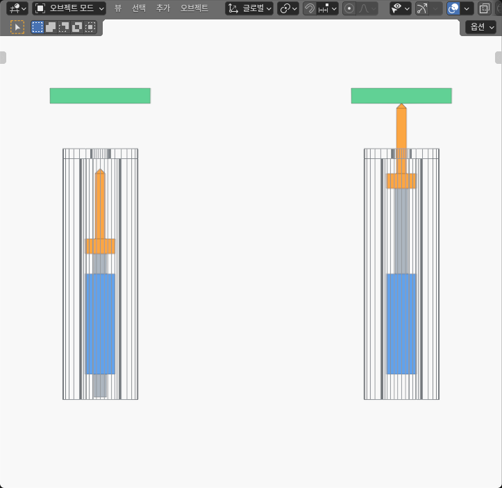
The wire display is only a viewing choice. It did not remove the housing or nose from the geometry checks, and the image itself was not used to decide containment.
A hidden tip did not prove that the whole load fitted
Checking only the tip would have been too weak. The loaded envelope also included the rod, head and shank. We recovered those components from the evaluated meshes and checked them against the finite housing and nose cavity.
In the retracted cell, every rod and fastener component stayed within the cavity’s axial range and polygonal interior. In the extended cell, the rod and head remained inside, but the shank crossed the nose plane and the tip lay outside. That is why the full-assembly containment result changed even though the same external body surrounded both cells.
The guide also needed its own check. The measured polygon-boundary gap between the rod and guide was about 0.199 mm in both states. Their static axial overlap was about 40 mm when retracted and 23 mm when extended. These values describe our finite authored geometry; they are not fit recommendations or manufacturing tolerances.
Across the moving rod, head, shank and tip versus the housing, nose, guide and target, no checked pair had a bounded positive-volume solid intersection. Containment and solid interference are different relations: a shaft can lie inside an open bore without intersecting the bore’s surrounding material.
The scene used 16 closed meshes and 1,370 evaluated vertices across the two static conditions. We independently reconstructed the axis, nose plane, cavity limits, guide opening and fastener datums. The 4 micrometre coordinate allowance and 8 micrometre comparison allowance were digital consistency bounds, not claims about hardware accuracy.
Reaching the target plane was not engagement
The extended tip landed at the target entry plane within the numerical comparison bound. Its cone cross-section at that plane was effectively zero, so the result establishes reach to the entry datum, not insertion into the target.
That distinction prevents a useful envelope result from becoming a fastening claim. We did not model thread contact, bit engagement, screw retention, preload, torque or final seating. The separate article on blind-hole bottoming and head seating begins later in the process, after a screw has entered a hole whose depth can constrain it.
External access is another independent check. Our whole-driver enclosure access experiment asks whether the complete driver can reach a recessed fastener through an opening. Here, the housing stayed fixed and only the internal loaded state changed.
The 30 mm vendor statement is not our screw dimension
OnRobot’s Screwdriver getting-started page, dated September 20, 2021 and checked October 8, 2026, states that screws up to 30 mm long are withdrawn inside the screwdriver during movement. The page shows no revision identifier.
We used that statement only to motivate the transfer-versus-working-state question. Our 34 mm overall fastener length, 28 mm bearing-face-to-tip length and 26 mm difference between static positions are original model inputs. They are not OnRobot dimensions, and our generic housing does not reproduce or validate that product.
The experiment also does not show that a retracted screw is retained, protected from every collision or safe during a robot move. The source claim and our geometry answer different questions: the source describes a product behavior; our scene shows how internal position changes a declared loaded envelope.
Model every allowed internal state before planning the move
For a loaded screwdriver or similar tool, one collision model may be insufficient. A practical check is:
- Define the internal states the process can actually command or report.
- Recover the tool axis and exit plane from the finite model in one frame.
- Check the complete moving assembly against the cavity and guide in the transfer state.
- Measure exposed reach and the target-plane relation in the working state.
- Use the resulting state-specific envelopes in path planning, then validate feed, retention, engagement and tightening separately on the real system.
Our two cells answer only the geometry question. The retracted state contained the full loaded assembly; the extended state provided 18 mm of exposed tip reach and touched the target entry datum without establishing engagement. No continuous shuttle motion, controller, transfer route, screw feed, force, torque, hardware performance or safety behavior was tested.