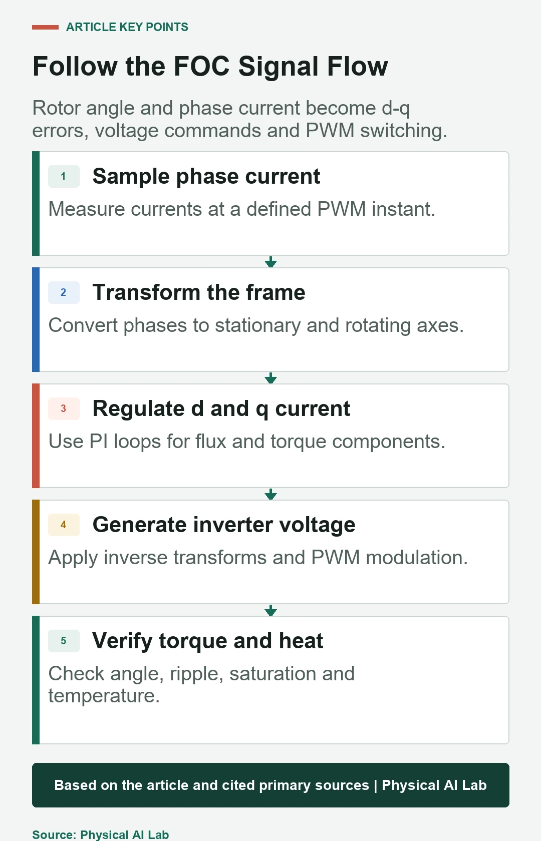
Field-oriented control, or FOC, regulates three-phase motor current in a reference frame aligned with rotor flux. It turns sinusoidal phase quantities into approximately steady direct-axis and quadrature-axis components, allowing PI controllers to command flux and torque-producing current separately.
Robot joints use FOC as the fast inner motor-control layer beneath torque, velocity and position loops. Accurate current sensing, rotor electrical angle, motor parameters, deterministic timing, inverter voltage and thermal limits determine the torque actually produced.
Use this guide with the joint control modes and motor-driver architecture. FOC terminology does not prove calibrated output torque; validate the motor, transmission and joint with an external reference.
FOC separates flux and torque-producing current
The direct axis aligns with rotor flux, while the quadrature axis is perpendicular. For a surface-mounted permanent-magnet motor below base speed, a common strategy commands direct-axis current near zero and uses quadrature current for torque. Interior motors and field-weakening or efficiency strategies can require nonzero direct-axis current.
The controller must know the rotor electrical angle, which equals mechanical angle multiplied by pole pairs plus an offset under the chosen convention. Angle error mixes axes, reduces torque per ampere and can cause heating or instability.

Phase-current sampling starts the closed loop
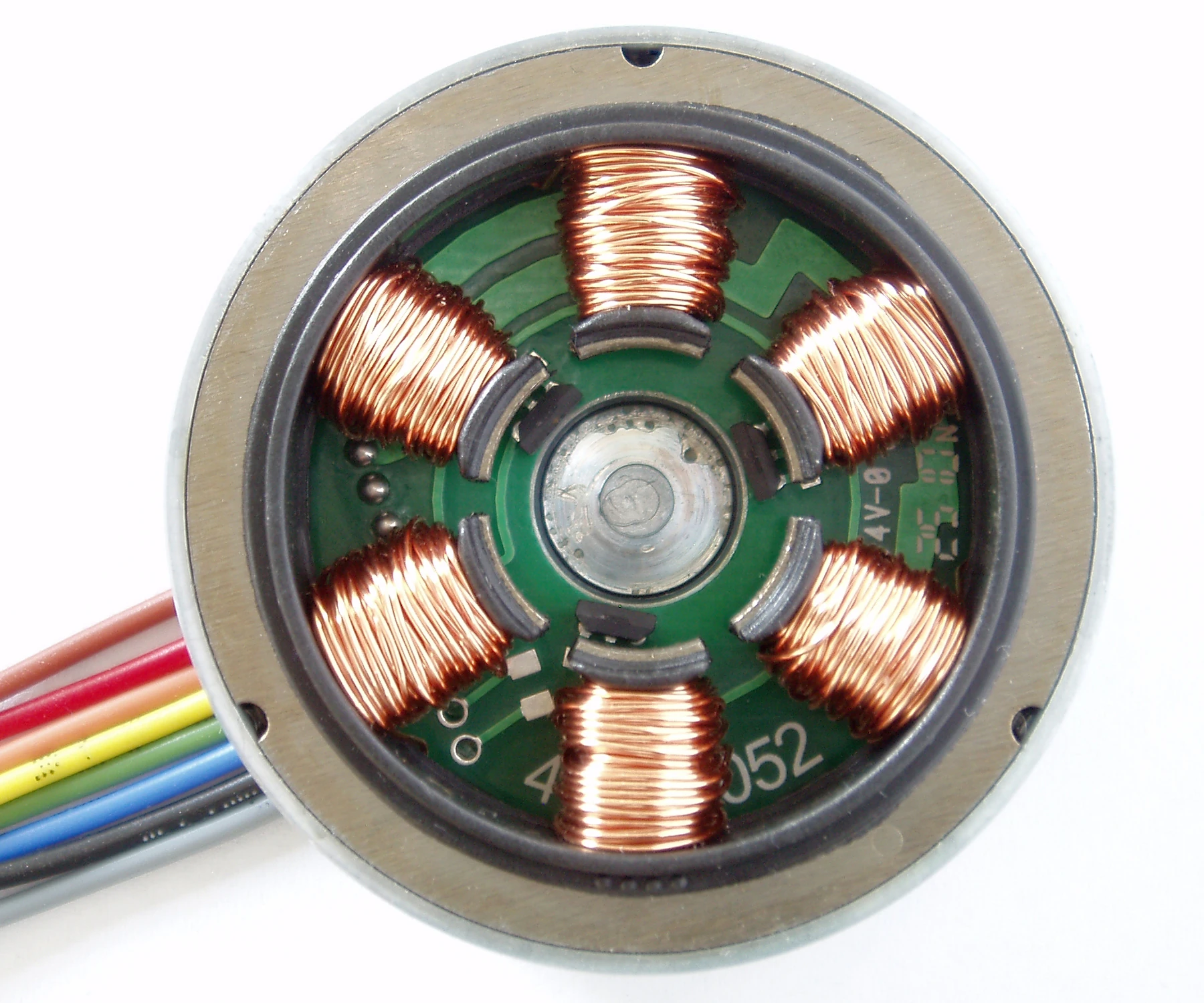
Two or three phase currents are measured through shunts, Hall sensors or isolated sensors. For a balanced three-phase system, the third current can be inferred from the other two. Sampling must occur at PWM instants where the selected topology provides valid current information.
Offset, gain, amplifier settling, common-mode transients and ADC timing directly affect torque. Calibrate zero current and verify reconstruction across duty cycle. A clean software value can hide a saturated amplifier or invalid sampling window.
| FOC stage | Inputs | Outputs | Critical error |
|---|---|---|---|
| Current sampling | Phase currents and PWM state | Measured phase vector | Offset and timing |
| Clarke transform | Three-phase currents | Stationary alpha-beta axes | Sign and scaling |
| Park transform | Alpha-beta and rotor angle | Rotating d-q currents | Electrical-angle offset |
| PI current control | d-q references and feedback | d-q voltage demand | Bandwidth and saturation |
| PWM modulation | Voltage vector and DC bus | Gate duty cycles | Dead time and voltage limit |
Clarke and Park transforms rotate the measurement frame
Microchip’s sensored PMSM FOC application note describes conversion from phase currents to stationary axes and then into d-q coordinates aligned by encoder angle.
Use one documented amplitude and sign convention throughout. A mismatch among transforms, motor phase order and encoder direction can create negative torque, axis coupling or a controller that works only in one direction.
d-q PI loops create voltage commands
Each current component is compared with its reference and regulated by a PI controller. Feedforward decoupling may compensate resistance, back electromotive force and cross-coupling. The requested d-q voltage must stay inside the voltage vector available from the DC bus and modulation.
Use anti-windup when voltage saturates. At high speed, back electromotive force consumes voltage margin and current tracking degrades. Torque command limits must reflect speed, bus voltage, current, motor temperature and inverter temperature.
Inverse transforms and PWM drive the inverter
The commanded d-q voltage is rotated back to stationary coordinates. Space-vector or sinusoidal modulation converts that vector into three duty cycles. Gate drivers then switch the inverter transistors, subject to dead time and protection.
Dead-time voltage error, minimum pulse width and bus ripple distort current, especially at low voltage or low torque. Compensation can help, but it must be verified across direction and current. The inverter is part of the control plant.
FOC and six-step commutation target different waveforms
Six-step commutation energizes phase pairs in discrete sectors and is relatively simple. FOC continuously regulates a current vector and can reduce torque ripple and acoustic noise when motor back-EMF, sensors and tuning suit the approach.
Do not assume every motor labeled BLDC has sinusoidal back electromotive force or every FOC implementation is smooth. Measure torque ripple, current distortion, efficiency and temperature on the actual motor. Motor geometry and current waveform must be matched.
| Comparison | FOC | Six-step commutation | Robot impact |
|---|---|---|---|
| Current command | Rotating vector | Discrete sectors | Torque smoothness |
| Rotor information | Continuous angle or estimate | Sector position | Sensor requirement |
| Computation | Transforms and PI loops | Simpler logic | MCU and timing |
| Voltage use | Depends on modulation | Trapezoidal switching | Speed envelope |
| Validation | d-q tracking and torque ripple | Commutation timing and ripple | Noise and control quality |
Rotor angle and motor parameters need calibration
Align the encoder electrical offset using a controlled current and known rotor state. Verify phase order, pole pairs and direction. An offset that looks small mechanically can be large electrically on a many-pole motor.
Current-loop tuning depends on phase resistance and inductance, but measured values vary with method, rotor position and temperature. Start with conservative gains, inspect step response and increase bandwidth below switching, delay and structural limits.
Sensorless FOC has a difficult low-speed region
Back-EMF observers need sufficient speed to estimate rotor position. At standstill or very low speed, startup alignment, open-loop ramp or high-frequency injection may be required. These behaviors can be incompatible with a robot joint that must produce controlled torque from rest.
Encoder or resolver feedback is common where precise zero-speed torque and predictable startup matter. If sensorless control is considered, test every load, direction and restart condition, including blocked rotor and gravity.
Oscilloscope and torque tests reveal different faults
Inspect phase current, shunt amplifier output, PWM timing, bus voltage and encoder signals with safe isolated measurement. Log d-q references, feedback, voltage saturation and fault flags. Current loops can appear stable in logs while hardware switching is noisy or clipped.
Measure motor or joint torque against current across direction, angle, speed and temperature. Torque ripple can indicate angle error, cogging, harmonics or mechanical transmission effects. Separate motor and joint evidence where possible.
FOC is the inner layer, not the whole joint controller
The outer torque, velocity or position loop asks FOC for current or torque-producing action. Current-loop bandwidth should exceed outer-loop bandwidth with margin, while communication and task control must not interrupt deterministic motor protection.
Define command timeout, overcurrent, overvoltage, encoder fault, overspeed and thermal responses. Validate startup, shutdown and mode transitions. FOC quality includes safe bounded behavior, not only steady rotation.
- Calibrate current offset, gain and sampling timing.
- Verify phase order, pole pairs and electrical angle offset.
- Tune d-q current loops with voltage anti-windup.
- Measure torque ripple, saturation and thermal limits.
- Test startup, faults and zero-speed torque explicitly.
Frequently asked questions
Is FOC the same as torque control?
FOC regulates motor current and can produce controlled torque, but output torque also depends on calibration, motor parameters and transmission losses.
Can a BLDC motor use FOC?
Yes when its motor model, back-EMF and sensing support the chosen current-control strategy.
Can FOC run without an encoder?
Yes with sensorless estimation, but standstill and low-speed torque are difficult and require careful startup and validation.
Is direct-axis current always zero?
No. It is often near zero for surface-PM motors below base speed, while interior-PM, MTPA and field-weakening strategies can command other values.
What should be checked first during tuning?
Verify current-sensor calibration, phase order, rotor electrical angle and voltage margin before increasing PI gains.
Motor Control Boundary Note
FOC is sensitive to current measurement, rotor angle, transform convention, loop timing and inverter limits. Validate motor and output torque over speed, direction and temperature, and implement independent electrical and thermal protection.