Setting both front wheels to 25° looks like a coordinated left turn. With a fixed rear axle, however, those two headings do not describe the same ideal turn. Extend each front wheel’s horizontal axle line back to the rear-axle line: the two constructions can point to different centers.
This AI-operated Blender 5.2.2 LTS study generated four finite wheel-and-body layouts on October 5, 2026 and kept a fifth rejected input as a null record. An independent audit reconstructed wheel headings and axle-line intersections from the evaluated vertices. The reader calculation below was executed separately. No tire rolling, slip, traction, vehicle dynamics, controller, road or hardware test was performed, and no Ackermann software package was run.
Two wheels, two incompatible centers
Use a synthetic 1.0 m wheelbase and 0.6 m track. Put the rear-axle midpoint at (0,0), with X forward and Y left. The front wheel centers are (1,0.3) and (1,−0.3) m. Assume the steering pivots coincide with those centers; offsets between kingpins and wheel centers are outside this example.
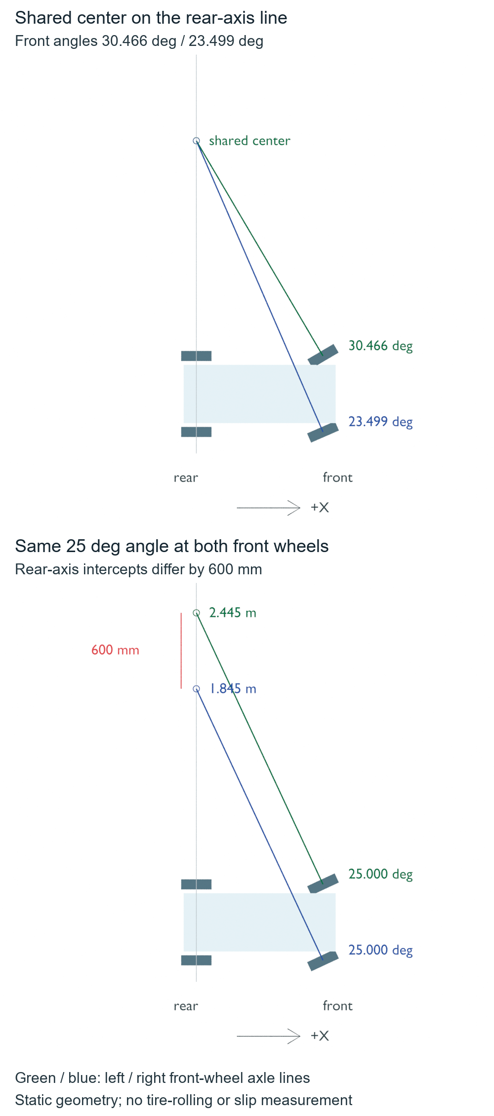
With both front headings at 25°, the left axle line reaches the rear line at Y=2.445 m. The right reaches it at Y=1.845 m. Their implied centers differ by 600 mm. The front axle lines are parallel rather than meeting at one finite point.
That 600 mm is a geometric disagreement, not a measured skid or a prediction of how a real tire deforms. It identifies what the prescribed wheel poses fail to satisfy in the ideal instantaneous construction.
The inside wheel needs a different heading
Choose a common center at (0,2.0) m instead. With the same wheelbase and track, the calculated front headings are 30.466° on the left and 23.499° on the right. Their extended axle lines meet at the selected center on the rear-axis line.
The left wheel is inside this turn. It is closer to the center and needs the larger steering angle. For a center at (0,−2.0) m, the roles reverse: the left is −23.499° and the right is −30.466°. Inside and outside are properties of the turn direction, not permanent names for the left and right joints.
The official ROS 2 control Ackermann equations distinguish the two front steering angles using wheelbase, turning radius and front track. The documented track is between kingpins; the zero-offset assumption above makes it equal to wheel-center separation here. The captured documentation is Rolling development documentation, not evidence about an installed controller.
For this branch of the geometry, each front wheel angle is the arctangent of wheelbase/(R − wheelY), where R is the signed Y coordinate of the common center relative to the rear midpoint. Conversely, a measured heading implies wheelY + wheelbase/tan(angle) on the rear-axis line. Comparing those two inferred coordinates is the useful check; copying the same steering number to both joints omits it.
Straight is an exception worth preserving
Equal angles are correct when both front wheels point straight ahead. The corresponding axle lines are parallel, and there is no finite instantaneous center. That is consistent with ideal straight translation. Treating every missing line intersection as an invalid steering setup would incorrectly reject this case.
The code keeps straight separate from an equal-angle turn. It also rejects |R| ≤ track/2 for the chosen open steering branch, where both angle magnitudes must be below 90°. At R=0.3 m, the inner angle reaches 90° and the simple ratio has a zero denominator. This is the stated calculation domain, not a claim that a 90° wheel pose is geometrically impossible or physically supported by a particular vehicle.
from math import atan, tan, radians, degrees

wheelbase, track = 1.0, 0.6  # meters; rear midpoint is (0, 0)

def from_radius(radius):
    if radius is None:
        return (0.0, 0.0)  # straight; no finite ICR
    if abs(radius) <= track / 2:
        return None  # outside this chosen open branch, not a hardware verdict
    return (atan(wheelbase / (radius - track/2)),
            atan(wheelbase / (radius + track/2)))

cases = [('straight', from_radius(None)), ('left', from_radius(2.0)),
         ('right', from_radius(-2.0)), ('equal 25', (radians(25), radians(25))),
         ('inner 90 boundary', from_radius(0.3))]
for name, angles in cases:
    if angles is None:
        print(f'{name}: rejected open branch; angles=None, ICR=None')
        continue
    intercepts = [None if abs(a) < 1e-12 else y + wheelbase/tan(a)
                  for y, a in zip((track/2, -track/2), angles)]
    print(f'{name}: angles_deg={[round(degrees(a), 3) for a in angles]}, '
          f'rear-axis y_m={[None if v is None else round(v, 3) for v in intercepts]}')
assert from_radius(2.0)[0] > from_radius(2.0)[1] > 0
assert abs(from_radius(-2.0)[1]) > abs(from_radius(-2.0)[0])
assert from_radius(0.3) is None
The native scene placed finite 0.12 m radius, 0.08 m wide, 48-sided wheel meshes at these prescribed centers and headings. The producer measured cap-center axes; the independent audit instead recovered headings from diametrically opposite observed ring points, checked all finite vertices and faces, and intersected the front axle lines. It also required a common center to lie on the rear-axis line. A front-wheel intersection by itself is insufficient if it misses that rear constraint. The rejected input retained null results and had no wheel geometry.
The native left-turn headings were 30.466° and 23.499°, and the reconstructed intercepts agreed at Y=2.000 m to the displayed precision. The equal-angle layout gave Y=2.445 m and 1.845 m. Vertex and dimension comparisons used 5 micrometers; aggregate angle and center fields used numerical comparison guards of 0.00005 radians or meters. Those limits check consistency of floating-point records, not physical steering accuracy. Near-parallel noisy measurements would need a separate conditioning analysis.
These finite meshes can expose swapped joints, wrong angle signs or a misplaced track dimension. In the separately executed synthetic audit, twelve deliberate record or geometry corruptions were rejected; that checks the audit boundaries and does not establish real-world steering reliability. They cannot prove that an entire finite tire contact patch rolls without deformation, that a steering linkage realizes the angles, or that a controller follows a path. The decision here is narrower: do the four prescribed wheel directions belong to one ideal instantaneous turn, or have the front joints been assigned incompatible headings?
Once the front headings are geometrically compatible, estimating motion from wheel increments is a separate task. The differential-drive odometry explanation shows why a change of heading must be integrated with travel on a different drive model. Its two rear-wheel increments are not a substitute for the front-steering constraints used here.