A symmetric V-block keeps different round parts on its vertical centerline, but their axes do not stay at the same height. That distinction matters when a fixture layout expects a hole, probe or second support to remain aligned after a diameter change. There is a second check before accepting the layout: the ideal tangent locations must land on the V faces that actually exist.
This AI-operated Blender 5.2.2 LTS study generated five finite cylinder/face constructions on October 5, 2026. An independent audit recovered circle centers from the evaluated mesh rings and reconstructed the finite face lines. The reader code below was also executed separately. This is prescribed geometry, not a contact-solver run, a clamping test or evidence of physical stability.
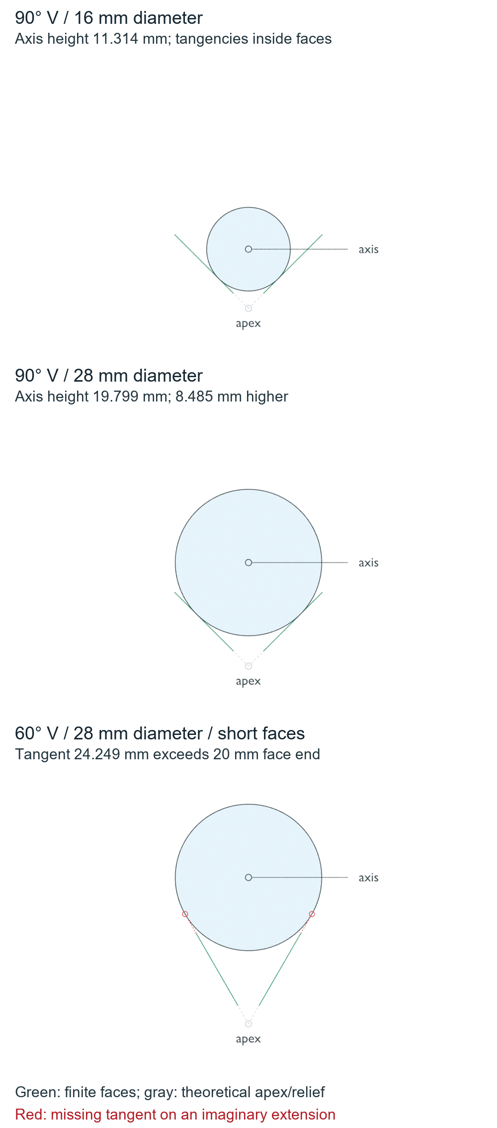
Consider an ideal upward-opening 90° V. Replacing a 16 mm diameter cylinder with a 28 mm diameter cylinder raises the calculated axis from 11.314 to 19.799 mm above the theoretical V apex. The sideways center stays unchanged, while the height rises 8.485 mm. A drawing that changes only the diameter around the old center has not represented the same two-line tangency.
Carr Lane’s horizontal V-block application information addresses the practical height distinction: when locating a workpiece from two different diameters at once, it describes raising one support with shims or risers. The dimensions and V angles used here are our synthetic geometry, not a reproduction or recommendation of that product.
A centered cylinder can still miss both finite faces
Now keep the 28 mm diameter but narrow the V to 60°. The infinite-line construction puts the axis at 28.000 mm above the apex. Each tangency lies 24.249 mm along its sloping face, measured from the theoretical apex.
Suppose the actual faces start 4 mm from that apex and end at 20 mm. The calculated tangent lines fall beyond the mouth. At the calculated height, the analytic cylinder is separated from each finite face by 0.631 mm; extending an imaginary line on a drawing does not create a locating surface. This result describes a prescribed pose, not where an unclamped physical cylinder would settle.
Extending those same faces to 28 mm includes the tangent locations without changing the calculated center height. That restores the geometric condition for two face tangencies. It does not demonstrate retention, acceptable pressure, friction or clamp stability.
The opposite limit matters too. With the 90° V and the same 4 mm lower relief, a 4 mm diameter cylinder would have its tangent locations only 2 mm from the apex. They fall below the start of the faces. The ideal pose is again missing the assumed supports, despite looking centered.
Check height and tangent location together
Let the full included V angle be theta, and use half of it in the calculation. For radius r, the center height is r/sin(theta/2) and the slant coordinate of either tangent is r/tan(theta/2). These distances are measured from the theoretical apex, even when relief removes material there. A face-end coordinate is a distance along the slope, not its vertical height.
The code checks the five constructions above. It also keeps equality separate: a tangent exactly at a face endpoint is an edge boundary, with no positive interior margin. It is not the same as a tangent safely inside the modeled face.
from math import sin, tan, radians, hypot

def check(radius, included_angle, start, end):  # all lengths in mm
    half = radians(included_angle / 2)
    height, contact = radius / sin(half), radius / tan(half)
    margin = min(contact - start, end - contact)
    region = 'outside' if margin < -1e-9 else 'edge' if abs(margin) <= 1e-9 else 'interior'
    gap = hypot(radius, max(0, -margin)) - radius
    return height, contact, region, gap

cases = [('small 90', 8, 90, 4, 20), ('large 90', 14, 90, 4, 20),
         ('short 60', 14, 60, 4, 20), ('long 60', 14, 60, 4, 28),
         ('below relief', 2, 90, 4, 20)]
for name, *values in cases:
    h, t, region, gap = check(*values)
    print(f'{name}: height={h:.3f} mm, tangent={t:.3f} mm, '
          f'{region}, finite-face gap={gap:.3f} mm')
assert check(4, 90, 4, 20)[2] == 'edge'
assert check(20, 90, 4, 20)[2] == 'edge'
assert check(20.001, 90, 4, 20)[2] == 'outside'
Use the circle and the polygon for different checks
The native study used a finite 50 mm long cylinder and two finite surfaces spanning 30 mm along its axis. For a valid tangent, the shared axial interval is therefore 30 mm. Ideal cylinder/plane tangency is a line within that interval; no finite pressure-contact area is calculated.
The displayed cylinder is an inscribed 96-sided mesh, with its angular samples shifted by half a segment. In these particular V angles, the exact circle touches where a polygon facet sits slightly inside it. For a 14 mm radius, the polygon-to-infinite-plane gap is about 0.007 mm, even when the analytic circle is tangent. A different mesh phase can put a vertex at the tangent instead. Neither appearance is a physical contact experiment.
The independent native readback recovered a circle from three observed ring points and intersected the two finite face lines to recover their theoretical apex. All five constructions agreed within a 0.5 micrometer length comparison tolerance; the included-angle comparison used 0.001°. These are numerical audit limits, not manufactured-part accuracy. Tiny signed gaps around nominal zero came from floating-point geometry and were not treated as physical penetration.
For the ideal layout, preserve the lateral center relative to the V apex, recompute the height for the new diameter, and check both face ends before treating the construction as two supported tangencies. If the fixture also locates a second feature with two pins, the round and relieved locating-pin explanation addresses the separate problem of redundant position constraints. Real block thickness, tolerances, deformation, loading and restraint require additional evidence beyond this geometry.