Ball screws and planetary roller screws convert rotary motion into linear motion with rolling contact. Ball screws recirculate balls between screw and nut; roller screws use multiple threaded rollers to create many contact lines. Both require guidance, bearings, lubrication and a holding strategy.
Roller screws can offer high load density and life in demanding packages, while ball screws are mature, efficient and widely available. Neither is universally better. Lead, thrust, speed, stroke, duty, preload, buckling, critical speed and maintenance decide the actuator.
Connect the choice to the joint actuator testing guide and brake and safe-stop guide. Gravity-loaded axes require application-specific protection against unintended motion.
Both mechanisms convert screw rotation into nut travel
Lead defines the linear travel per screw revolution. Motor torque produces axial thrust through the mechanism’s mechanical advantage and efficiency. Smaller lead increases force multiplication and resolution but reduces linear speed at a given motor speed.
Define which member rotates and which translates. Nut rotation, screw rotation and inverted arrangements change inertia, critical speed, bearings and cable routing. Include the guide that reacts side load.

Ball screws rely on recirculating rolling elements
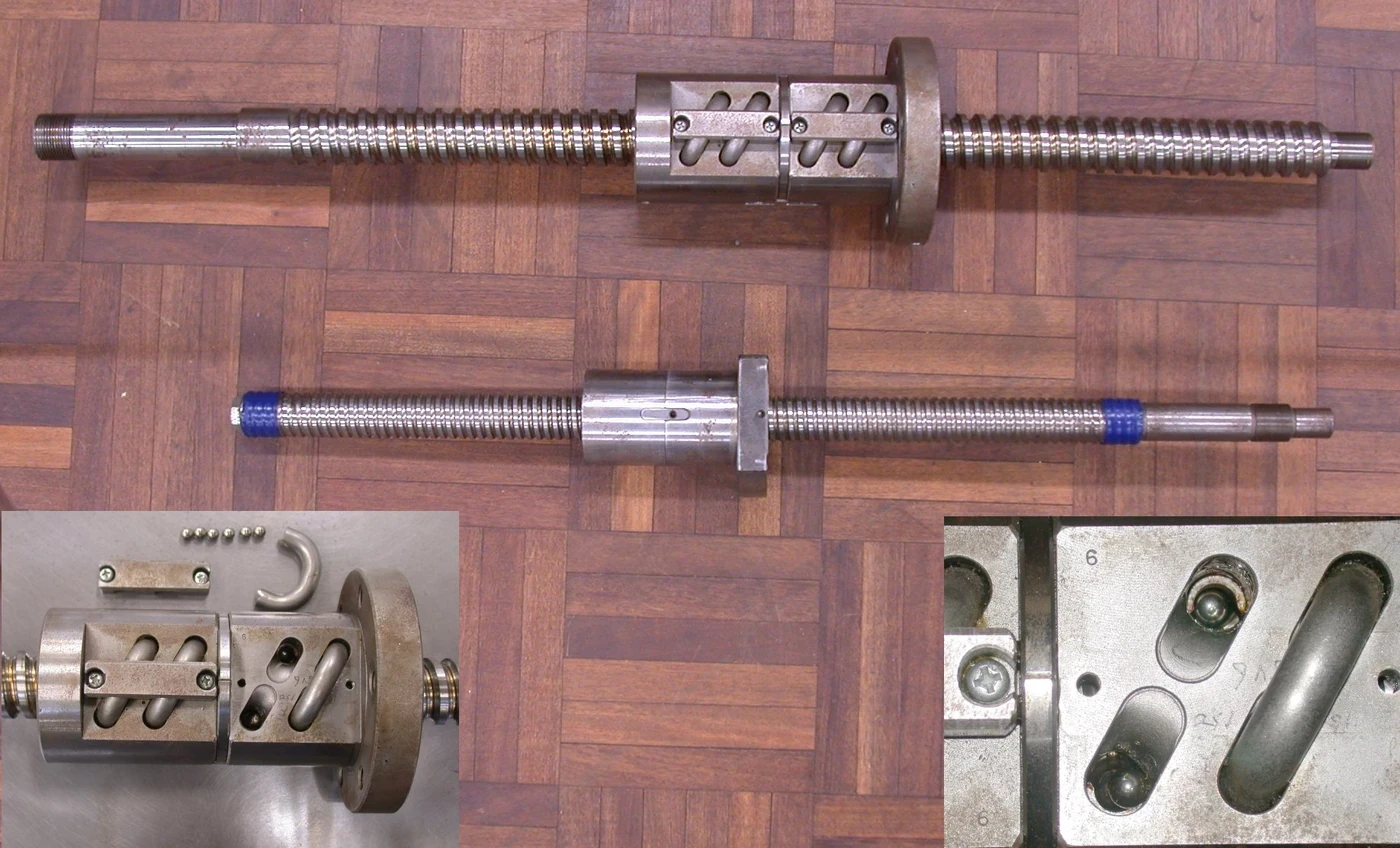
THK’s selection guidance treats load, life, accuracy, preload, buckling and permissible rotational speed as linked design checks. Balls roll through the loaded raceway and return path.
Return-tube or internal-return geometry affects nut size, speed, noise and assembly. Ball diameter, contact angle, groove accuracy, preload and lubrication determine stiffness and efficiency. Use the exact product’s dynamic-load and life method.
| Selection dimension | Ball screw tendency | Roller screw tendency | System check |
|---|---|---|---|
| Contact | Recirculating balls | Multiple threaded rollers | Load distribution |
| Load density | Broad practical range | Can be high in compact form | Exact product rating |
| Efficiency | Generally high | Design dependent | Measured duty map |
| Noise and return behavior | Return path matters | Roller synchronization matters | Speed test |
| Cost and availability | Often favorable | Often higher and specialized | Lifecycle value |
Roller screws use multiple threaded contacts
Planetary roller screws place threaded rollers between nut and screw. Multiple contact lines can support high axial load and stiffness in a compact diameter. Roller geometry and synchronization make manufacturing and lubrication demanding.
Do not generalize all roller-screw architectures. Planetary, recirculating and inverted arrangements differ. Ask for allowable speed, load spectrum, life, preload, efficiency and service under the actual stroke and orientation.
Lead couples thrust, speed and reflected inertia
Small lead increases thrust per motor torque but demands more motor revolutions for the same linear speed. Large lead supports speed and can reduce motor speed, but requires more torque for a given thrust.
Lead also changes reflected linear mass, backdrive behavior and position sensitivity. Optimize the motor, drive and screw together. A high-force small-lead actuator may overheat because the motor and screw cycle rapidly.
Preload trades axial play for friction and heat
Preload can reduce axial clearance and improve stiffness or reversal repeatability. It raises contact stress, friction and temperature, and reduces life if excessive. Thermal expansion can change preload in a constrained mounting.
Measure drag and stiffness after assembly and through temperature. Do not use screw preload to compensate for flexible guides, couplings or bearings. Preserve alignment to avoid side loading the nut.
Buckling limits compression on long screws
A slender screw under compressive thrust can buckle before the rolling contacts reach their catalog capacity. THK instructs designers to calculate buckling and permissible compressive or tensile load for the actual support distances and end conditions.
Check the worst extended position, guide alignment and impact factor. Changing the fixed-free or fixed-supported arrangement changes capacity. The structure that carries the bearing blocks must sustain the assumed boundary condition.
Critical speed limits long rotating screws
A rotating screw has bending critical speeds that depend on length, support and diameter. Operation near resonance causes vibration and can damage bearings or the nut. Longer stroke and higher speed make this a primary constraint.
Use manufacturer permissible-speed calculations with safety margin and the actual mounting. Consider rotating-nut or linear-motor alternatives when a long screw would exceed critical speed. Balance, straightness and coupling alignment matter.
| Failure mode | Primary driver | Design check | Test evidence |
|---|---|---|---|
| Buckling | Compression and free length | Euler or product method | Proof load with margin |
| Critical speed | Rotation and support span | Permissible-speed method | Vibration sweep |
| Nut overheating | Load, speed and preload | Duty thermal model | Steady-cycle temperature |
| Side loading | Guide misalignment | Guide and mount analysis | Wear and torque |
| Backdrive or drop | Lead, friction and gravity | Holding risk assessment | Power-loss test |
Linear guides must carry side loads and moments
Screw-nut contacts are intended primarily for axial load. A separate guide should react lateral force, moment and alignment error. Binding and uneven wear result when the screw is forced to serve as a structural guide.
Align bearing blocks, guide rails and nut mount through the full stroke. Measure motor current and thrust in both directions. A local current rise can reveal misalignment, contamination or damaged return elements.
Backdrivability changes the safe holding strategy
Rolling screws can backdrive when external axial load produces screw torque, especially with larger lead and high efficiency. Do not assume a screw is self-locking. Power loss on a vertical axis can create hazardous motion.
Use a properly rated holding brake, counterbalance, mechanical restraint or other risk-controlled architecture. Validate brake timing, drop distance, wear and restart. Friction that happens to hold a new actuator is not a safety function.
Selection ends with the full duty-cycle test
Compare thrust, speed, stroke, lead, preload, efficiency, inertia, critical speed, buckling, life, lubricant, contamination, noise, mass and service. Include motor, coupling, supports, guides, brake and structure.
Run representative motion and load to thermal steady state, then inspect accuracy, drag and wear. Repeat after life exposure. Choose the screw that meets the whole actuator requirement with margin, not the one with the highest isolated thrust rating.
- Translate robot motion into thrust, speed and stroke.
- Choose contact architecture and lead together.
- Check preload, buckling and critical speed.
- Keep side load out of the screw nut.
- Validate power-loss holding and lifecycle behavior.
Frequently asked questions
Is a roller screw always stronger than a ball screw?
No. Exact size, architecture, load spectrum, speed, lead, preload and life determine capacity.
Do ball screws always have high backlash?
No. Preloaded ball screws can have low axial play, but friction, life and the rest of the actuator must be considered.
Will a rolling screw hold position when power is off?
Do not assume so. Efficient screws can backdrive and gravity axes need a verified holding strategy.
Is a smaller lead always better?
No. It increases force multiplication but limits speed at a given motor rpm and changes inertia, efficiency and heat.
Does every screw actuator need a linear guide?
It needs a structure that carries side loads and moments without forcing them through the screw nut; a dedicated guide is the usual solution.
Linear Actuator Safety Note
Vertical and gravity-loaded screw actuators can move when drive torque is removed. Use a task-specific risk assessment, rated holding or counterbalance system, verified stop sequence and current product calculations for buckling, speed and life.