A blind hole can be deep enough for the center of a screw tip and still be too shallow for the tip’s outer edge. In the synthetic assembly here, a hole extends 18 mm to its deepest point. A 28 mm fastener above a 12 mm plate-and-washer stack appears to need only 16 mm of that depth. Yet its flat end reaches the conical bottom while the head remains 0.5 mm above the washer.
The missing dimension is the available depth across the finite tip, rather than at the hole’s centerline. A section view can expose the error before a simple length subtraction accepts the assembly.
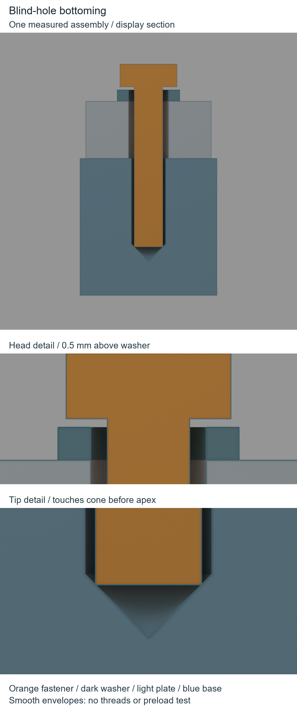
The deepest point is not a seating surface
The example hole has a 3 mm radius and a cylindrical wall 15 mm deep. Its conical bottom adds another 3 mm at the axis. The fastener’s flat tip has a 2.5 mm radius. At that radius, the cone provides only 15.5 mm of usable axial depth.
All of these dimensions, including the deliberately chosen 90° included cone angle, are synthetic. The shape is not a drill specification. The shaft and hole are smooth geometric envelopes with no helical threads; they do not constitute a functioning threaded joint. Their purpose is to isolate bottom interference from other fastening questions.
NASA’s current NASA-STD-5020B, section 4.7.5b treats contact with the bottom and interference with incomplete internal threads as separate conditions to avoid in its spaceflight-fastener scope. This calculation addresses only the former. It does not borrow the standard’s authority to approve a joint or supply a minimum thread-engagement rule.
Here, length is measured from the head’s flat bearing face to the tip. The stack includes a 10 mm plate plus its washer. Using the head’s top as the length datum, or leaving the washer out of the stack, would answer a different geometry question.
Which surface touches first?
Lower the envelope along the common hole axis. There are two candidate stopping positions: the head meets the washer, or the flat tip meets the cone. The first geometric contact is the higher of those two head positions. It is not a simulated torque-controlled stop.
| Length below head | Complete stack | Head gap at first contact | Remaining axial travel to bottom |
|---|---|---|---|
| 26 mm | 12 mm | 0 mm | 1.5 mm |
| 27.5 mm | 12 mm | 0 mm | 0 mm: simultaneous touch |
| 28 mm | 12 mm | 0.5 mm | 0 mm: tip touches first |
| 28 mm | 13 mm | 0 mm | 0.5 mm |
These are computed ideal geometry results. The simultaneous-contact row has no positive bottom reserve. Forcing the third row’s head down to the washer places the tip 0.5 mm beyond its permitted axial position; the original apex-only check would still report 2 mm available.
The thicker-stack row changes the washer from 2 to 3 mm while keeping the 28 mm envelope. It shows why the whole assembly matters. It is not a recommendation to add a washer: the study has not established complete-thread engagement, runout clearance, preload or joint strength for either stack.
Run the short calculation in Python; all dimensions are in millimetres:
R, a = 3.0, 2.5           # mm: hole and flat-ended tip radii
cylinder, cone = 15.0, 3.0
usable_depth = cylinder + cone * (1 - a / R)

for name, length, stack in [
    ('short', 26.0, 12.0),
    ('simultaneous touch', 27.5, 12.0),
    ('bottom first', 28.0, 12.0),
    ('thicker stack', 28.0, 13.0),
]:
    first_stop = max(stack, length - usable_depth)
    head_gap = first_stop - stack
    bottom_reserve = usable_depth - (length - first_stop)
    print(f'{name}: head gap {head_gap:.3f} mm; '
          f'axial bottom reserve {bottom_reserve:.3f} mm')

print(f'Point depth {cylinder + cone:.3f} mm; '
      f'finite-tip depth {usable_depth:.3f} mm')
assert usable_depth == 15.5
assert (cylinder + cone) - (28 - 12) > 0  # misleading apex-only check
assert usable_depth - (28 - 12) < 0      # forced head seating interferes
print('These are geometric contacts, not tightening or preload results.')
What the finite model must preserve
A point at the tip is insufficient for this check. An AI-operated Blender 5.2.2 LTS study kept four complete assemblies, each with a finite smooth fastener envelope, washer, plate and blind base. It recorded 21 prescribed static configurations: five axial positions for each case, plus the deliberately intersecting forced-seat control. A separate audit matched all evaluated world vertices, matrices, faces, edges, pose identities and CSV results against independently reconstructed geometry. The four exported assemblies were restored to their respective first-contact poses. No keyframed insertion or tightening simulation was run.
The independent checker obtains the limiting depth from the actual cone-face planes at every tip vertex, then compares that position with the actual washer top and head underside. The actual readback rounded to a 0.500 mm head gap in the bottom-first case and 0.500 mm of axial bottom reserve with the thicker stack. A 0.0002 mm numerical comparison guard handles floating-point boundary residuals; it is not a manufacturing tolerance and does not turn simultaneous touch into positive clearance.
The reported bottom reserve is remaining axial translation, not the shortest distance to the sloping cone and not a physical penetration measurement. The 64-sided tip and cone use a matching angular grid. A separate offline control rotates the polygonal tip by half a sector and detects the resulting change in contact depth. That difference belongs to mesh discretization, not hardware accuracy.
For this strictly coaxial translation, the geometric constraints vary linearly with axial position, so a noninterfering path to first contact can be checked without inventing a tightening simulation. Threads, fillets, chamfers, deformation and tolerances could introduce earlier restrictions in an actual assembly. Even when the head and washer planes coincide over a bearing area, geometry alone has not demonstrated clamping force.
In a CAD review, identify the head’s bearing datum, include every layer in the stack, and inspect the bottom profile over the complete tip footprint. Keep positive bottom reserve separate from mere simultaneous touch, and keep both separate from the thread and load checks needed for the real joint. After choosing geometry that can seat, the separate whole-driver access study checks whether the tool can reach the fastener through the enclosure. A clear seating geometry does not supply that access.