A Geneva wheel that turns a quarter revolution and then stops can look finished in an animation. Before relying on that dwell, inspect what holds the wheel after the driving pin leaves the indexing region. A constant rotation value on the timeline is a command to stay still; it is not a mechanical constraint.
That distinction changes what belongs in the model. A conventional Geneva drive uses the pin and slots for indexing, with separate blocking surfaces retaining the wheel between steps. NPTEL’s indexing-mechanism lesson identifies the blocking disk, while CMU’s mechanism text, section 8.4 describes the corresponding recessed surfaces and the clearance around the driving pin. The synthetic geometry below deliberately omits those locking surfaces so that their absence can be tested.
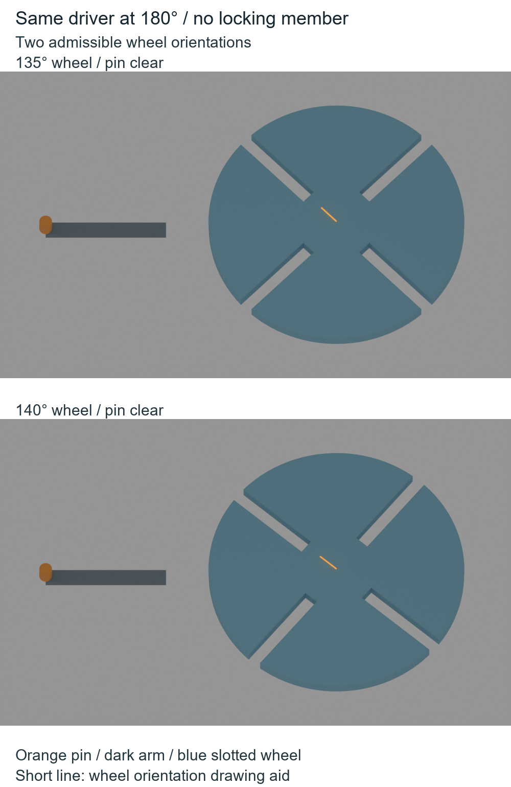
Two different wheel angles fit the same stopped driver
Place the shaft centers 80 mm apart, with the pin orbit radius set to 80/√2 = 56.569 mm. Use a 3 mm pin radius and a slotted wheel contained within a 60 mm outer radius. These are study dimensions, not a manufactured Geneva specification.
At a driver angle of 180°, the pin is on the side farthest from the driven shaft. Its center is 136.569 mm from that shaft. Even after subtracting the pin and wheel radii, there is at least 73.569 mm of separation. This bound does not depend on the wheel’s angle.
The wheel can therefore occupy the intended 135° orientation or a wrong 140° orientation without hitting the pin. Both are geometrically admissible at the same driver position. The pin has no way to select the intended dwell angle there. This does not show how far a real wheel would drift: there is no friction, bearing, inertia, load or blocking disk in the calculation.
Where the quarter-turn comes from
For the nominal index interval, from driver −45° to +45°, aim the active radial slot along the line from the driven shaft to the pin. That line changes from 225° through 180° to 135°: one clockwise 90° index. Its angular derivative reaches zero at the two interval boundaries.
Outside that interval, this model prescribes the wheel angle to stay at the respective endpoint. The resulting 270° holding interval is an input to the construction. It is not a solved dwell, and finite pin entry or exit need not occur at precisely the nominal centerline angles. In particular, a centered pin with lateral clearance does not establish driving contact.
The following Python uses millimetres and reproduces the index angles and the two admissible hold poses. It does not implement a Geneva contact solver:
import math

C = 80.0  # mm; all dimensions below are synthetic
r = C / math.sqrt(2)
pin_radius, wheel_radius = 3.0, 60.0

def wheel_angle(driver_degrees):
    t = math.radians(max(-45, min(45, driver_degrees)))
    return 180 - math.degrees(math.atan2(r * math.sin(t), C - r * math.cos(t)))

for driver in (-45, 0, 45, 180):
    print(f'driver {driver:4d} deg -> prescribed wheel {wheel_angle(driver):7.3f} deg')

# At 180 degrees the pin is farthest from the driven-wheel center.
# The entire finite wheel lies within wheel_radius, regardless of its angle.
hold_bound = C + r - pin_radius - wheel_radius
for extra in (0, 5):
    angle = wheel_angle(180) + extra
    print(f'hold wheel {angle:.3f} deg: pin-to-wheel lower bound {hold_bound:.3f} mm')
assert hold_bound > 0
assert abs(wheel_angle(-45) - wheel_angle(45) - 90) < 1e-10
print('Both hold angles are pin-clear; no locking member is modeled.')
The last two numeric lines give wheel angles of 135.000° and 140.000°, both with the same 73.569 mm lower bound. The code intentionally cannot choose which wheel angle a free mechanism will take.
Check the slot mouth before trusting the route
The finite route still needs checking: an attractive centerline animation could hide a pin cutting through the wheel. Here the wheel has four open, straight-sided 7 mm slots. Each flat root lies 18.431 mm from the shaft along its slot. The wheel is 6 mm thick; the 8 mm high pin passes through that thickness. The driver arm sits below it. Rounded roots, locking recesses and manufacturing features are omitted.
The AI-operated Blender 5.2.2 LTS study recorded 184 prescribed static configurations of the same assembly: three finite solid parts—the driver arm, pin and four-slot wheel—and two edge-only measurement references. It did not bake a keyframed animation or run a contact solver. A separate audit matched evaluated world vertices, matrices, edge and face topology, the pose identities and the CSV at every configuration. The two actual hold orientations were approximately 135.000011° and 139.999987°. Their pin-envelope margins were 73.568539 mm and 73.595174 mm, both consistent with the orientation-independent 73.569 mm explanation after rounding.
The independent mathematical check follows the entire prescribed cycle against the finite polygonal wheel outline. It uses the 3 mm circular envelope around the actual 64-sided pin, so positive clearance also clears that inscribed pin mesh. At 0.1° sampling, the smallest envelope margin is approximately 0.396 mm near the slot mouth, just outside the nominal index interval. A bound on how fast the pin and wheel boundaries can move between samples leaves a conservative 0.220 mm positive minimum for this mathematical route. The 184 native readbacks are a coarser static grid, whose smallest observed envelope margin was approximately 0.422475 mm at driver +48°. The 0.220 mm continuous bound comes from the separate mathematical path check, not from interpolation of those Blender poses. The auditor’s numerical guards compare the stated construction with readback; they are not manufacturing accuracy. These are synthetic geometry results, not measured part clearances.
The boundary checks matter. A 6 mm slot reaches geometric touch at the centered pose; a 5 mm slot fails the finite-pin check. Increasing the wheel’s outer radius to 65 mm while keeping the same straight slot shape causes an exit-mouth envelope intersection. Those are failure controls, not alternative production designs. A negative envelope margin is not a measured penetration depth or a force result.
When reviewing a Geneva model, inspect the indexing route and the dwell constraint separately. Preserve the slot/pin clearance check, then identify the actual blocking surfaces that retain the wheel and clear each other during indexing. If the only explanation for the stationary wheel is a clamped angle or a flat keyframe segment, the model has demonstrated a prescribed motion sequence, not a mechanically locked dwell.
The slider-crank and Scotch-yoke timing study explains near-end residence without a finite stationary dwell. Here the separate question is which mechanism actually retains an indexed wheel. The finite yoke-slot study gives another example of checking the whole pin before trusting a centerline path; that clearance check still does not supply the missing Geneva lock.