At a middle pitch of +90 degrees, XYZ Euler coordinates lose one independent instantaneous angular direction. The object’s orientation does not become invalid. Instead, two coordinate changes affect the orientation along the same line of rotation, leaving only two independent directions in the local angle-to-orientation map.
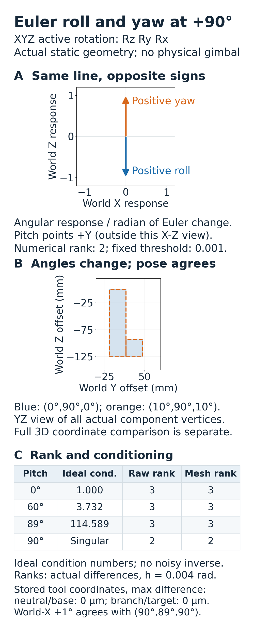
The signs matter. Under the convention used here, a positive roll change and a positive yaw change act in opposite world directions at +90-degree pitch. Adding both by the same amount can leave the entire tool orientation unchanged. This is a property of the coordinates, not a test of a robot’s joints or a physical gimbal.
An AI-operated Blender 5.2.2 LTS experiment on October 6, 2026 compared 31 static poses. Rotation matrices and independently reconstructed tool geometry gave matching results: the angular-coordinate map lost one independent direction at +90-degree pitch. The experiment tests coordinate representation, not a robot or controller.
Ten degrees of roll and yaw can cancel
Use active, right-handed rotations acting on column vectors. A local tool point becomes a world point through a rotation followed by a common translation. Define the rotation as R = Rz(yaw) Ry(pitch) Rx(roll): the rightmost roll matrix acts on the point first. This explicit equation matters more than assuming that every interface gives the label XYZ the same meaning.
Start at the Euler triple (0, 90, 0) degrees. At this orientation, the positive roll spatial-angular axis is world −Z, while the positive yaw axis is world +Z. The pitch axis is world +Y. Roll and yaw are therefore antiparallel, not two independent directions and not identical signed commands.
For the ideal rotation matrices, (10, 90, 10) degrees gives the same orientation as (0, 90, 0). The common roll and yaw increments cancel exactly in the mathematical model. Changing only the sign of yaw to give (10, 90, −10) does not cancel them. At −90-degree pitch the sign relationship changes again: the roll axis aligns with positive world Z, so opposite roll and yaw increments form the neutral combination.
The Blender 5.2 rotation manual describes the hierarchy of Euler axes and their dependence at gimbal lock. Here, the explicit active-matrix convention supplies the signed result. The manual’s general axis-alignment explanation is not used as evidence that equal positive X and Z commands always have the same effect.
The reference tool used a 125 × 31.25 × 31.25 mm rectangular main body and an offset 31.25 × 31.25 × 62.5 mm tab. Both closed cuboid meshes shared each pose and a common origin at (125, −62.5, 125) mm. Comparing all 16 transformed vertices included the asymmetric tab rather than relying on one axis or a symmetric silhouette. These are prescribed component meshes; this is not a manufactured tool, Boolean-union or contact experiment.
For the native base and neutral pair, the largest raw rotation-matrix component difference was approximately 7.59e-9. Every recorded corresponding world-vertex coordinate agreed exactly at its stored precision. That is equality of the returned stored coordinates, not zero physical error or a claim of micrometer measurement accuracy.
A one-degree world-X orientation still has an Euler representation
At the exact +90-degree coordinate singularity, the instantaneous roll, pitch and yaw directions span world Y and Z. That does not mean a different valid orientation about world X has ceased to exist.
Take the base rotation and pre-multiply it by a world-X rotation of +1 degree. The resulting matrix is still a proper rotation. In the declared convention, it also equals the Euler triple (90, 89, 90) degrees. That is a finite orientation comparison: a one-degree change of the tool can correspond to a large change of the chosen Euler numbers near this coordinate branch.
Pre-multiplication is part of the question. Multiplying the same X rotation on the right instead describes a local-axis composition and generally gives a different result. The native study retained the left operand, cached base matrix and direct product separately from the Euler conversion of the alternative triple. The largest component difference between their raw matrices was approximately 4.29e-8. All corresponding recorded world vertices agreed at stored precision, and the independent relative-matrix angle was approximately 1 degree. No expected matrix replaced the API output.
Neither representation proves that a physical robot can reach the orientation, follow a path to it, avoid a collision or remain within joint limits. No inverse-kinematics solver or controller is included. The conclusion concerns representability and the local coordinate map.
Near the singularity, specify what is becoming poorly conditioned
At zero roll and yaw, the three spatial-angular columns are (cos(pitch), 0, −sin(pitch)), (0, 1, 0) and (0, 0, 1). They describe angular change per Euler-angle change, with all angles in radians. At +90 degrees, the first and third columns are opposites and the ideal map has rank 2.
For pitches of 0, 60 and 89 degrees, the ideal map’s 2-norm condition numbers are approximately 1, 3.732051 and 114.588650. These quantify the sensitivity of this angular coordinate map. They are not condition numbers for a robot’s physical joint-to-tool Jacobian. At exactly 90 degrees the ideal map is singular, so there is no finite analytic condition number.
Native floating-point values need a different description. A stored approximation to pi/2 and its trigonometric results need not produce an exactly zero matrix component. In the actual 90-degree sample, the roll column included a small world-X component of approximately −4.37e-8 rad/rad. The independent comparison used the frozen 0.001 numerical rank threshold. It did not invert a noisy near-singular matrix or report an infinite measured native rate.
| Pitch | Ideal angular-map condition | Numerical rank, both reconstructions |
|---|---|---|
| 0 degrees | 1.000000 | 3 |
| 60 degrees | 3.732051 | 3 |
| 89 degrees | 114.588650 | 3 |
| 90 degrees | Singular; no finite value | 2 |
The condition column is analytic. The rank column comes separately from the actual API matrices and the actual finite-body edge reconstruction, with the same fixed threshold. It should not be used as a controller tuning value or a robot-joint performance ranking.
The samples independently perturbed each Euler coordinate by ±0.004 rad around the four center poses. The matrix calculation used the skew part of (R_plus − R_minus) R_center^T / (2h) to obtain spatial-angular columns. A separate reconstruction used three labeled orthogonal edges of the actual finite main body to recover the rotation before taking the same differences. For this fixed-axis perturbation, the finite central difference includes the known sin(h)/h factor. The step is an angle increment, not a time interval or measured angular velocity.
The largest component error against the analytic columns with that step factor was about 2.14e-6 rad/rad for the raw matrices and 3.31e-5 rad/rad for the finite-mesh reconstruction. Both were below the predeclared 5e-4 rad/rad comparison bound. These are numerical angular-map comparisons, not measured tool-position accuracy or physical tolerances.
This short standard-library example expresses the analytic comparisons without Blender. It uses elementary matrix multiplication and reports numerical identity residuals alongside the ideal coordinate-map condition numbers. It makes no native API or controller calls.
import math

def multiply(a, b):
    return [[sum(a[i][k]*b[k][j] for k in range(3)) for j in range(3)] for i in range(3)]

def xyz(roll_deg, pitch_deg, yaw_deg):
    r, p, y = map(math.radians, (roll_deg, pitch_deg, yaw_deg))
    cr, sr, cp, sp, cy, sy = math.cos(r), math.sin(r), math.cos(p), math.sin(p), math.cos(y), math.sin(y)
    rx = [[1, 0, 0], [0, cr, -sr], [0, sr, cr]]
    ry = [[cp, 0, sp], [0, 1, 0], [-sp, 0, cp]]
    rz = [[cy, -sy, 0], [sy, cy, 0], [0, 0, 1]]
    return multiply(rz, multiply(ry, rx))

def largest_difference(a, b):
    return max(abs(a[i][j]-b[i][j]) for i in range(3) for j in range(3))

base = xyz(0, 90, 0)
neutral = xyz(10, 90, 10)
target = multiply(xyz(1, 0, 0), base)  # World-X rotation is on the left.
branch = xyz(90, 89, 90)
print("same-sign roll/yaw neutral error:", largest_difference(base, neutral))
print("finite branch versus world-X target error:", largest_difference(branch, target))
print("opposite-sign roll/yaw changes pose:", largest_difference(base, xyz(10, 90, -10)))
for pitch in (0, 60, 89, 90):
    if pitch == 90:
        print("90 deg: ideal rank 2; no finite analytic condition number")
    else:
        p = math.radians(pitch)
        condition = (1+abs(math.sin(p)))/abs(math.cos(p))
        print(f"{pitch} deg: analytic angular-coordinate condition={condition:.6f}")
The study compared 31 static poses at frame 1 in separate collections at the same origin. The Euler API reference specifies radians and rotation order. These pose alternatives were compared separately; they do not constitute playback, interpolation or simultaneous physical tools.
Using a different orientation representation can avoid this particular Euler-coordinate chart, but it does not remove every representation decision. For example, quaternion sign and interpolation path require their own treatment. When a tool behaves unexpectedly near a 90-degree middle angle, separate the intended orientation from the coordinate increments and the frame in which those increments are defined.