A force expressed in tool axes can be correct while its accompanying moment still refers to the sensor origin. That pair mixes two different descriptions of the load. Before rotating six numbers into a new frame, identify both the axes in which the components are expressed and the point about which the moment is taken.
An AI-operated Blender 5.2.2 LTS experiment on October 6, 2026 compared four static arrangements with a prescribed force acting at tool origin T and a free couple C. Closed mesh endpoints encoded the assigned force, moment and instantaneous rigid velocity field. An independent 3D reconstruction checked the reference points, frame axes and vector transforms. The resulting powers are model calculations, not sensor readings or physical power measurements.
Put the force and the reference point on the same sketch
Let r point from S to T, expressed in sensor axes. Let R_ST map tool-axis components into sensor-axis components. Thus its transpose maps sensor components into tool components. These definitions fix the direction of both the translation and the rotation; reversing either convention changes the equations.
Our force f_S acts at T, with components expressed in sensor axes. Its moment about S is r×f_S. The independent free couple C adds to that moment, so tau_S = C + r×f_S. About T, the point force contributes no moment because its lever arm is zero. Only the free couple remains, expressed in tool axes.
For a general wrench already known about S, the change is therefore f_T = R_ST^T f_S and tau_T = R_ST^T (tau_S − r×f_S). Subtract the old lever-arm contribution before expressing the remaining moment in the new axes. A free couple itself is independent of the reference point; the force’s contribution is what changes.
Modern Robotics, section 3.4 introduces moment as position crossed with force and derives wrench frame changes using the pairing between a wrench and a twist. The explicit S-to-T convention here supplies the signs in our example. We do not infer a particular robot interface’s component order from that general principle. This article writes a wrench as (moment, force) and its paired twist as (angular, linear).
Choose r = (0.125, 0.0625, −0.03125) m, f_S = (2, −4, −8) N and C = (0.25, −0.125, 0.375) N m. Then r×f_S = (−0.625, 0.9375, −0.625) N m, giving tau_S = (−0.375, 0.8125, −0.25) N m. With aligned axes, tau_T is simply C. Rotating tau_S alone would leave the sensor lever-arm contribution attached to the tool origin.
Next rotate the tool axes by +90 degrees about sensor Z. The same load has f_T = (−4, −2, −8) N and tau_T = (−0.125, −0.25, 0.375) N m. The second arrangement also rotated the entire sensor/body setup by +45 degrees in world coordinates. Endpoint reconstruction confirmed these sensor-to-tool component relationships within the fixed comparison bounds.
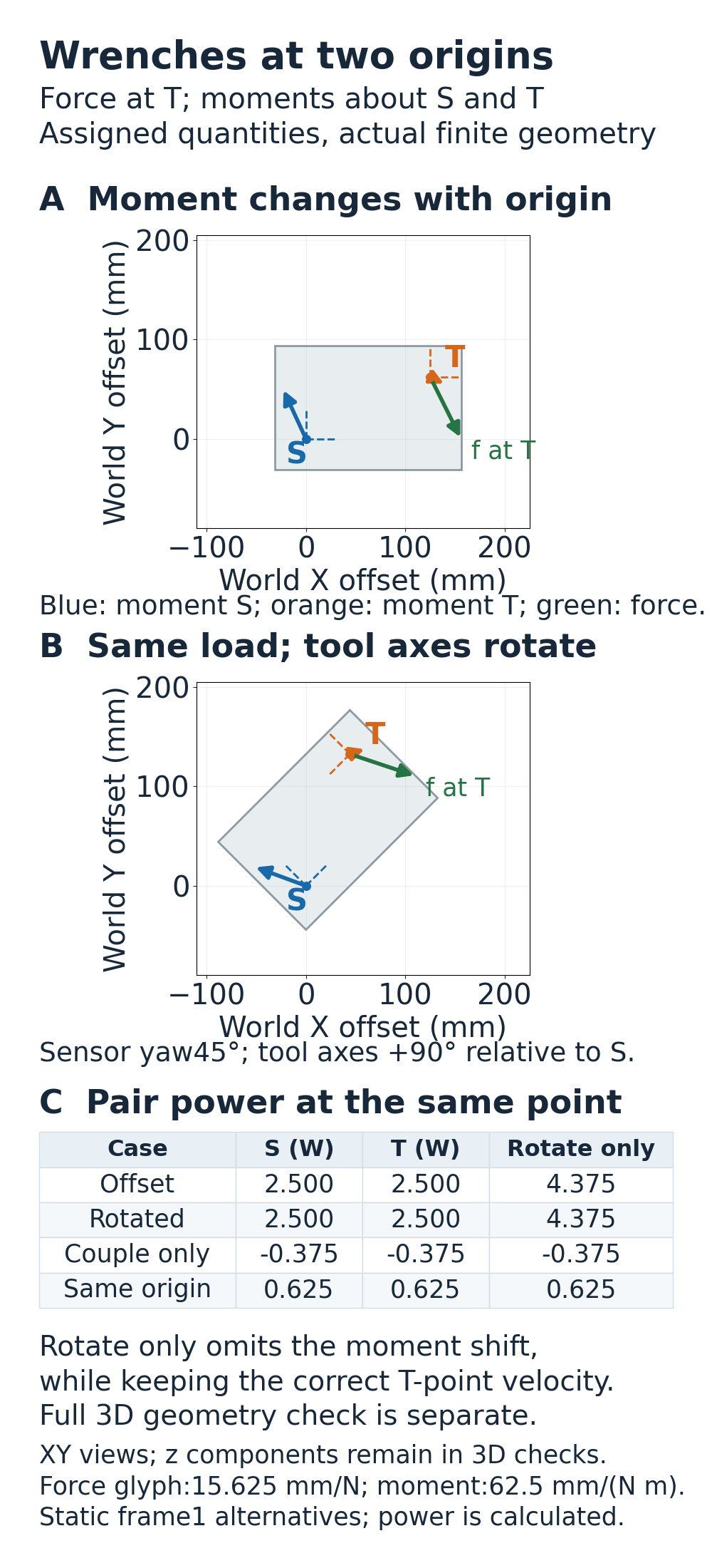
Pair each moment with the velocity of its own point
A useful sign check needs more than the wrench. Assign an instantaneous rigid velocity field with sensor-point velocity v_S = (0.25, 0.125, −0.125) m/s and angular velocity omega_S = (1, 2, −1) rad/s. The velocity at T, still expressed in sensor axes, is v_S + omega_S×r. Consequently, v_T = R_ST^T (v_S + omega_S×r) and omega_T = R_ST^T omega_S.
These velocity symbols are assigned values at one configuration. The retained scenes are static and no rate measurement is implied. They let us check the same model power at the two reference points: P = f·v + tau·omega.
For the offset example, the ideal power at both S and T is 2.5 W. If we rotate tau_S into tool axes without shifting its reference point, but use the correctly transported tool-point velocity, the result becomes 4.375 W. That mismatch exposes the mixed reference points. It is not a claim that a physical device gained power, nor is a single matching scalar sufficient to validate an arbitrary transform. The vectors and the lever arm must also be checked.
Two controls help interpret the correction. If the force is zero, the free couple only needs an axis rotation, even with separated origins. If S and T coincide, r is zero and both the moment shift and the point-velocity correction vanish. These are reasons rotation alone can be sufficient in particular cases; they do not justify dropping the translation term for an offset nonzero force.
Recovered-endpoint model calculations, rounded to six decimals:
| Arrangement | S (W) | T (W) | Rotate-only moment with T velocity (W) |
|---|---|---|---|
| Offset, aligned axes | 2.500000 | 2.500000 | 4.375000 |
| Offset, rotated axes | 2.500000 | 2.500000 | 4.375001 |
| Free couple only | -0.375000 | -0.375000 | -0.375000 |
| Coincident origins | 0.624999 | 0.625000 | 0.625000 |
The largest absolute difference between the matched S/T calculations was approximately 4.11e-07 W, below the predeclared 0.004 W comparison bound. Coordinates were checked with a 4 µm component allowance; frame and vector transports had separate fixed limits. These are calculation tolerances and stored-coordinate comparisons, not sensor accuracy or physical power precision.
Reproduce the ideal pairing before using measured data
The following standard-library code was executed separately for all four assigned cases. Its last column deliberately uses the rotate-only moment with the correct tool-point velocity. It uses elementary arithmetic and makes no Blender, sensor or robot-interface calls.
import math

def cross(a, b):
    return [a[1]*b[2]-a[2]*b[1], a[2]*b[0]-a[0]*b[2], a[0]*b[1]-a[1]*b[0]]

def add(a, b):
    return [x+y for x, y in zip(a, b)]

def dot(a, b):
    return sum(x*y for x, y in zip(a, b))

def tool_components(a, degrees):
    t = math.radians(degrees)
    c, s = math.cos(t), math.sin(t)
    return [c*a[0]+s*a[1], -s*a[0]+c*a[1], a[2]]

C, vS, omegaS = [.25, -.125, .375], [.25, .125, -.125], [1, 2, -1]
for name, r, fS, angle in [
    ('offset aligned', [.125, .0625, -.03125], [2, -4, -8], 0),
    ('offset rotated', [.125, .0625, -.03125], [2, -4, -8], 90),
    ('pure couple', [.125, .0625, -.03125], [0, 0, 0], 90),
    ('same origin', [0, 0, 0], [2, -4, -8], 90),
]:
    tauS = add(C, cross(r, fS))  # The prescribed force acts at T.
    fT = tool_components(fS, angle)
    tauT = tool_components(C, angle)
    vT = tool_components(add(vS, cross(omegaS, r)), angle)
    omegaT = tool_components(omegaS, angle)
    pS = dot(fS, vS)+dot(tauS, omegaS)
    pT = dot(fT, vT)+dot(tauT, omegaT)
    wrong = dot(fT, vT)+dot(tool_components(tauS, angle), omegaT)
    assert abs(pS-pT) < 1e-12
    print(f'{name}: S={pS:.6f} W, T={pT:.6f} W, rotate-only={wrong:.6f} W')
Each arrangement retained a finite reference body and closed endpoint markers for the frames and assigned vectors. Both force expressions were anchored at the prescribed application point T; moment and point-velocity markers used their named S or T origin. The independent checker recovered centers from all evaluated marker vertices before reconstructing axes, offsets and scaled vectors. It checked each vector transport separately, rather than accepting power equality alone. Zero force was recorded explicitly without an invented small arrow.
The four arrangements are separate alternatives at frame 1, sharing the same world coordinates. Their glyphs encode assigned quantities; they do not measure force, torque, velocity or physical power. No contact solver, sensor calibration, controller command, dynamics model or hardware trial was included. For a real interface, verify its stated axes, moment reference point, velocity reference point, units and component ordering together.
A representation change also cannot supply a physical torque that the contacts cannot produce. The separate two-contact gripper torque experiment examines that capacity question; this study only changes how an existing wrench is described.