A centered 100 N load does not, by itself, assign 25 N to each of four supports. In a rigid-platform model with upward-only vertical reactions, 25/25/25/25 N and 40/10/40/10 N can both satisfy the same force and moment equations at the same support positions. To predict which distribution a real assembly takes, you need information beyond its stationary shape.
This matters when a model reports that a platform is balanced and you then use one quarter of the load to size each foot, interpret a load cell, or compare an assembly. Equal sharing may be a useful additional assumption. It is not a result established by the centered load alone.
Consider a massless reference platform with four support points at x = ±0.3 m and y = ±0.2 m, all at z = 0. Number them around the rectangle: A is (+,+), B is (−,+), C is (−,−), and D is (+,−). A 100 N downward force acts at the center of the platform’s top, at (0, 0, 0.08) m. Platform weight is excluded; the stated force is the entire applied load in this example.
The support pads and plate have finite dimensions, but the reaction model supplies only four vertical force unknowns. It includes no support stiffness, deformation, friction, clamping force, or measured contact response. The calculations below use that specified model, not a test of a physical four-foot platform.
The opposite diagonal can take more without changing the balance
For an upward reaction F at (x, y, 0), the moment about the origin has components yF and −xF. The four forces must total 100 N, their moments about x must cancel, and their moments about y must cancel. Those are three independent equations for four unknowns.
The remaining freedom has a concrete shape. Add the same amount to A and C, and subtract it from B and D. Total upward force stays unchanged. Each diagonal also has opposite moment arms, so neither tilt moment changes. Using a parameter λ in newtons, the reactions are:
[FA, FB, FC, FD] = [25 + λ, 25 − λ, 25 + λ, 25 − λ] N
All five rows below balance the same centered load. They are alternatives, not forces to combine.
| λ (N) | A (N) | B (N) | C (N) | D (N) |
|---|---|---|---|---|
| 0 | 25 | 25 | 25 | 25 |
| +15 | 40 | 10 | 40 | 10 |
| −15 | 10 | 40 | 10 | 40 |
| +25 | 50 | 0 | 50 | 0 |
| −25 | 0 | 50 | 0 | 50 |
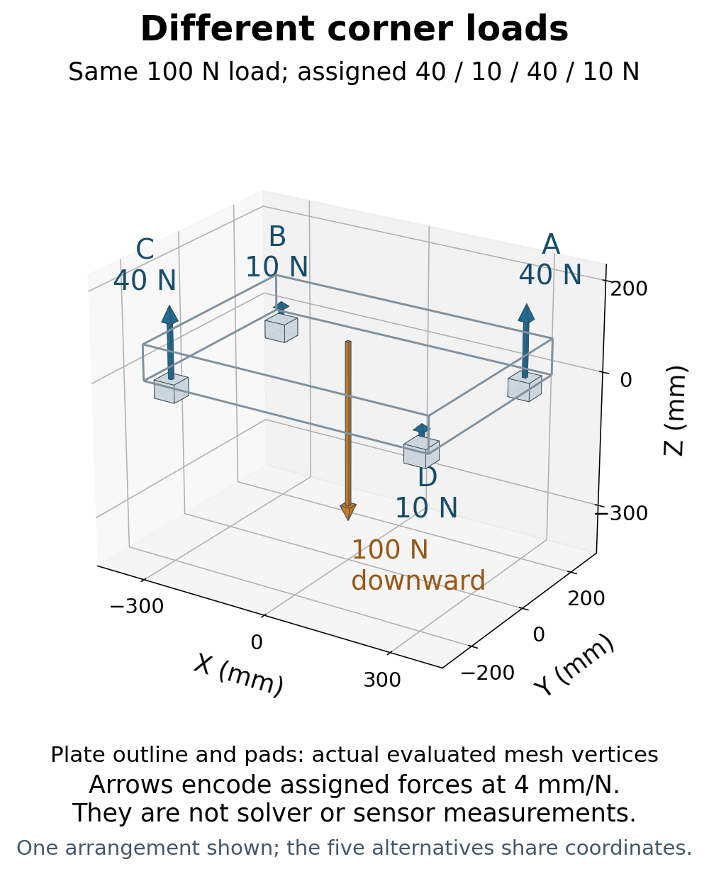
This is the missing constraint in a force calculation, not a hidden movement of the plate. The balance matrix has columns [1, y, −x], rank three, and a null direction [1, −1, 1, −1]. Moving along that direction changes the individual forces without changing the three balance results.
It is also why checking only the total load is inadequate. The different assignment 40/40/10/10 N still totals 100 N, but it leaves a 12 N·m moment about x. It is not a solution for this centered load. A load-sharing result needs both force and moment checks.
A zero reaction is an algebraic endpoint
The upward-only assumption restricts λ to −25 through +25 N, including both endpoints. At +25 N, B and D have zero reactions; A and C each carry 50 N. Increasing λ to 25.001 N would require B and D to pull downward, which this model excludes.
Zero does not prove that a pad has lifted, that a gap exists, or that the remaining contacts are stable. The geometry can place a pad at the reference plane while the algebra assigns it zero force. Deciding contact state requires further mechanical information.
An AI-operated Blender 5.2.2 LTS experiment on October 6, 2026 created and read back five independent prescribed arrangements at frame 1. Their collections share world coordinates so the plate and pads can be compared without relocating the load. They are not five simultaneous physical platforms. Arrow lengths encode assigned force values at 0.004 m/N; they are not a force reading from a solver. Each zero reaction uses an octahedral symbol with no arrow direction, rather than a tiny invented reaction arrow.
There is another important boundary: vertical-only forces do not establish horizontal restraint or resistance to yaw. Solving these three equations is not a demonstration of full three-dimensional stability.
What the geometry experiment actually checked
The finite reference plate is 0.68 × 0.48 × 0.08 m. Each pad is 0.05 × 0.05 × 0.04 m, with its top at z = 0. Across the five arrangements, the study retained 50 objects, 497 evaluated vertices and 413 faces, including every explicit zero-force symbol. It preserved the full meshes, transforms, source, inputs, geometry log, vertex CSV and scene library. The original scenes and context were checked before and after the run.
An independent audit used the actual pad-top vertices to recover support locations and the actual glyph tails and tips to reconstruct the encoded vectors. It checked all three force and all three moment components, then derived the rank-three matrix and its one-dimensional nullspace from the recorded lever arms. The largest net-force component was below 9e-6 N and the largest net-moment component below 7.1e-7 N·m. Those small residuals come from numerical representation of the prescribed geometry, including the downward glyph rotation; they are not physical load errors or measured sensor accuracy.
The comparison used predeclared 1 µm coordinate, 1e-4 N force and 1e-5 N·m moment limits. It also checked complete finite topology, matrices and local face normals. Standalone controls rejected 26 corrupted records and seven invalid inputs, including force assignments that preserve total load but violate moment balance. Those controls and a synthetic float32 proxy were calculations, not additional native or hardware experiments.
The result establishes consistency between the declared geometry, encoded assignments and equilibrium family. It does not select the real support loads: no contact, stiffness or deformation solver was called.
What would make one distribution the answer?
Equilibrium supplies necessary constraints, but it need not supply enough information to determine every reaction. MIT’s Mechanics and Materials I, Lecture 7 develops this point using spring systems: force–deformation relationships and compatibility are needed alongside equilibrium. Those 2006 teaching examples support the principle; they do not test this four-support apparatus.
For an actual platform, the missing information may include support compliance, plate deformation, initial support heights, preload, or measured reactions. Identical elastic supports at matched heights could justify a symmetric model with equal sharing, but those are additional assumptions to state and examine. A static drawing cannot establish them.
The contrast with a load carried by two shaft supports is useful. In that specified two-support model, force and moment equations determine the two signed reactions. Adding support locations does not automatically add enough independent equilibrium equations to determine each new force.
The short Python example below checks the five assignments with exact fractions. It has been executed as a standalone calculation. It does not call Blender, a contact solver, a sensor, or a stiffness model. The three residual entries are vertical force in N, followed by moments about x and y in N·m.
from fractions import Fraction as F

points = [(F(3, 10), F(1, 5)), (-F(3, 10), F(1, 5)),
          (-F(3, 10), -F(1, 5)), (F(3, 10), -F(1, 5))]
rows = [[F(1)] * 4, [y for x, y in points], [-x for x, y in points]]
null = [1, -1, 1, -1]
assert all(sum(a * n for a, n in zip(row, null)) == 0 for row in rows)

def residual(forces):
    return [sum(a * f for a, f in zip(row, forces)) - target
            for row, target in zip(rows, [100, 0, 0])]

for lam in [0, 15, -15, 25, -25]:
    forces = [25 + lam * n for n in null]
    assert min(forces) >= 0 and residual(forces) == [0, 0, 0]
    print(f"lambda={lam:+3d} N: {forces}; [Fz, Mx, My] residual={residual(forces)}")

bad = [40, 40, 10, 10]
assert residual(bad) == [0, 12, 0]
print("Same total, wrong moments:", bad, "residual=", residual(bad))
assert min(25 + F(25001, 1000) * n for n in null) < 0
print("lambda=25.001 N requires a negative reaction; excluded by this model.")
If a calculation returns 25 N per support, ask which condition selected that row. A symmetry assumption, a compliant model, or measured loads may provide an answer. The stationary geometry and centered load by themselves leave a family of answers.