An unobstructed line to a post does not guarantee that a scan samples it. In a model of zero-width rays, a 20 mm post at 3 m receives one sampled hit when its center lies on a scan direction, yet receives none after moving halfway between directions 0.5° apart. Every sampled ray can still return a valid background intersection. An empty place in the post’s sampled outline therefore need not be an occlusion or a range error.
An AI-operated Blender 5.2.2 LTS experiment on October 6, 2026 checked these four conditions with actual finite-mesh surface queries. The model uses zero-width rays: it has no laser spot, reflected signal or detection threshold. The results describe a stationary geometric sampling grid, not a physical LiDAR detection test.
A clear line that the scan never asks about
The official ROS LaserScan definition separates the scan’s starting angle, ending angle and angular distance between measurements. It defines angles around positive Z, with zero along X. We use those field meanings to specify a stationary horizontal grid from −2° to +2°. This is an input model, not a claim that a particular scanner implements every nominal direction with an infinitesimal beam.
The post is a closed, 600 mm tall, regular 64-sided prism inscribed in a 20 mm diameter circle. The sensor origin and all rays are at its mid-height. A finite wall begins at X = 4 m behind it. At 3 m center distance and 0° bearing, the grid’s 0° ray meets the post before the wall.
Move the post center to a bearing of 0.25°, keeping its center distance at 3 m and the grid unchanged. The nearest sampled directions are now 0° and 0.5°. Each passes 13.090 mm from the post center, farther than the post’s 10 mm circumradius. Both miss it.
The finite polygon occupies bearings of approximately 0.059° to 0.441°. Neither neighboring sample is in that interval. All nine scan rays reach the wall. A separate probe aimed directly at 0.25° meets the post, showing that the route is clear—but that probe is not one of the scan’s samples. Counting it would erase the very gap being tested.
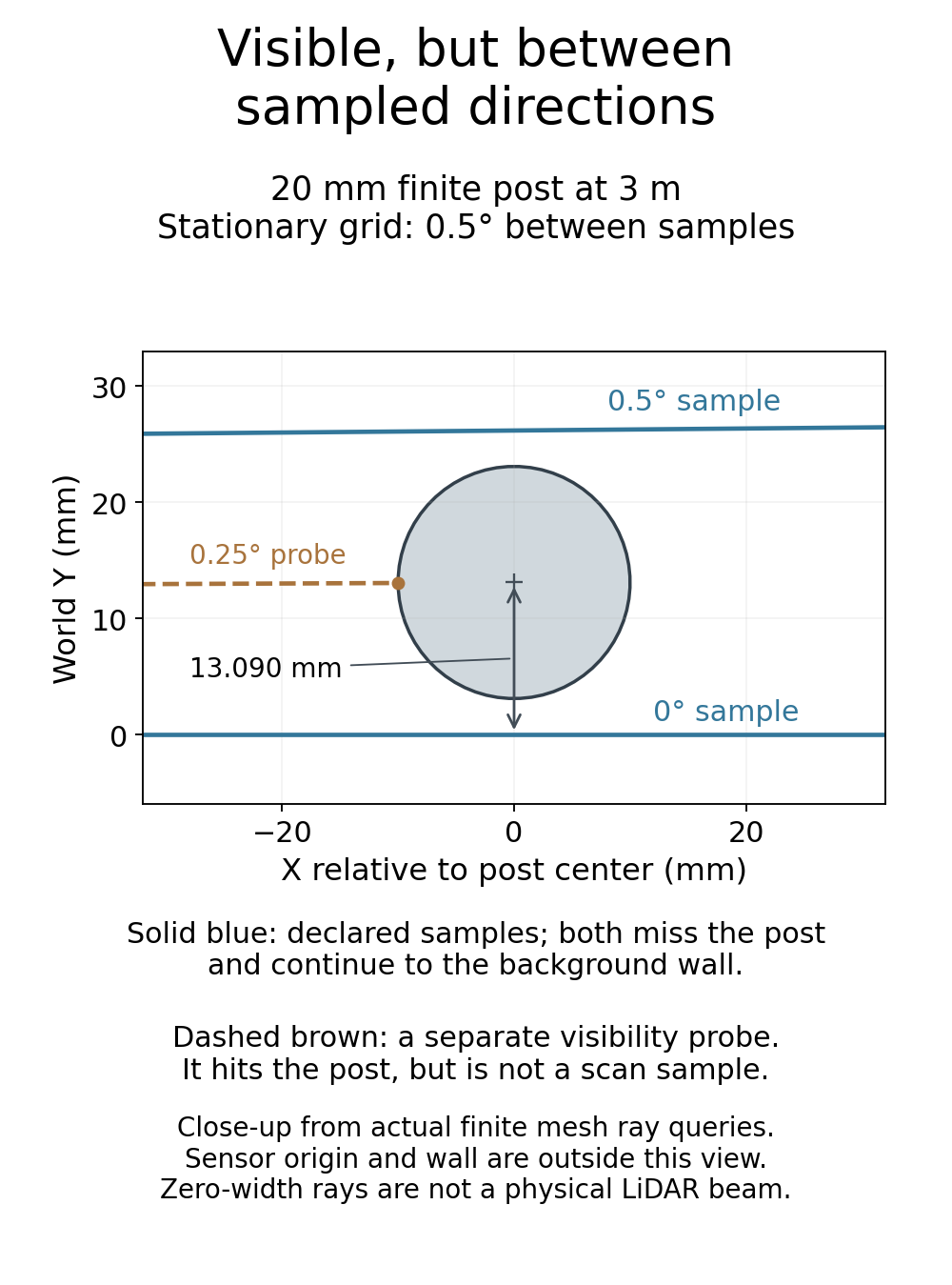
Change spacing or distance, then recount actual intersections
Reducing the grid spacing to 0.25° places a sample on the unchanged post bearing. The 17-ray scan then produces one post intersection. Alternatively, bring the post center to 1.5 m, retain its 0.25° bearing and keep the original 0.5° grid. Its finite angular span becomes about 0.763°, and the 0° and 0.5° rays both intersect it: two of nine samples hit the post.
These comparisons change how the same feature occupies the angular grid. They do not change the model’s range calculation: the nearest intersected surface is still found geometrically. Angular sampling and range accuracy are different questions. One sampled intersection does not establish reliable recognition or detection by a real device.
When checking a simulated scan layout, include the feature’s position between adjacent directions, not only a favorable case with a ray through its center. Keep a visibility probe separate from the sensor’s declared grid. A phase sweep can reveal a sampling gap that one centered test hides; the four cases here demonstrate that issue without claiming exhaustive coverage of every placement.
What the actual experiment checked
The experiment made 48 actual Scene.ray_cast calls: 44 declared scan rays and four separately tagged center-bearing probes. The coarse grids contain nine rays each; the finer grid contains 17. Across the scan rays, four hit the post and 40 hit the wall. The four probes all hit the post, but none contributes to those sample totals.
Each of the four stationary placements retained both closed meshes: the 128-vertex, 66-face post and an eight-vertex, six-face wall. The wall occupies X = 4 to 4.1 m and Y and Z = −0.5 to +0.5 m. Every ray starts at the origin, uses a normalized horizontal direction and has a 6 m query limit. The post uses a proper rotation about Z plus translation; the wall stays fixed. The study records four placements at Blender frame 1, not a timed scan or moving sensor.
An independent three-dimensional triangle calculation checked the first intersected object and face, returned point, normal, transform and geometric range for every query. It checked all 544 world-space vertex rows, complete finite faces and edges, local geometry, query ordering and the separate probe accounting. The API normals were compared with local face edges transformed by the recorded proper rotations; world-edge consistency was checked separately with bounds derived from endpoint rounding. The original 1 µm geometry, 20 µm intersection and 3e-5 normal-component tolerances were retained. These are numerical consistency limits, not a LiDAR accuracy or resolution specification.
Blender’s documented surface-ray query supplies a surface intersection tuple. Our range is the distance from the recorded origin to its returned hit point; no sensor-range API was called. A pinned source implementation documents direction normalization and the original-object reference. That source pin is a separate reference, not proof of the installed build’s identity; the actual runtime version, build hash and instance API documentation were captured with this experiment.
Standalone controls rejected 24 corrupted study records and five invalid inputs. Separate precision controls checked translated small faces and rejected 11 additional corruptions, including a normal just above the unchanged tolerance. Controls for maximum query range, a finite wall edge, post height and a complete geometric miss were calculations only; they were not additional native ray calls or hardware tests.
Reproduce the finite post cross-section
The following standard-library code clips each horizontal ray against the 64 sides of the same polygon. The origin is transformed into post coordinates; the ray range is limited to 6 m. It counts post intersections only. The separate three-dimensional audit also includes the finite post height and background wall.
from math import pi, sin, cos, radians

def hits_post(distance, bearing_deg, ray_deg):
    # Horizontal section of an inscribed 64-sided post, radius 0.010 m.
    # Post-local sensor origin is (-distance, 0); rays have zero width.
    a = radians(ray_deg-bearing_deg)
    dx, dy = cos(a), sin(a)
    apothem = 0.010*cos(pi/64)
    enter, leave = 0.0, 6.0
    for k in range(64):
        normal_angle = 2*pi*(k+1)/64
        nx, ny = cos(normal_angle), sin(normal_angle)
        rate = nx*dx + ny*dy
        remaining = apothem + nx*distance
        if abs(rate) < 1e-12:
            if remaining < 0:
                return False
        elif rate > 0:
            leave = min(leave, remaining/rate)
        else:
            enter = max(enter, remaining/rate)
        if enter > leave:
            return False
    return True

cases = [(3.0, 0.0, 0.5), (3.0, 0.25, 0.5),
         (3.0, 0.25, 0.25), (1.5, 0.25, 0.5)]
for distance, bearing, step in cases:
    angles = [-2+i*step for i in range(round(4/step)+1)]
    samples = sum(hits_post(distance, bearing, a) for a in angles)
    probe = hits_post(distance, bearing, bearing)  # Not an extra scan sample.
    print(f'distance={distance:.1f}m bearing={bearing:.2f}deg step={step:.2f}deg: samples={samples}, probe={probe}')
print(f'Far closest-ray distance: {3000*sin(radians(0.25)):.3f} mm')
The sample counts are 1, 0, 1 and 2; each center-bearing probe intersects the post. Using a finite polygon rather than calling it an exact cylinder also makes the model boundary explicit: its circumradius is 10 mm and its side distance from the center is about 9.988 mm.
For a real LiDAR, nominal angular spacing alone cannot supply a guaranteed minimum detectable object size. Beam footprint, return processing and surface response are absent here, so neither the missed centerline samples nor the recovered ones predict a product’s detection result. This calculation is useful for inspecting the angular grid in a ray-based model; a hardware detection claim needs the device’s documented conditions and separate evidence.
For broader sensor selection, the existing 2D versus 3D LiDAR guide explains scan geometry and coverage. This experiment adds a narrower check: given a chosen angular grid and feature size, vary the feature’s bearing within one sample interval and distinguish a valid background return from a sampled target intersection. For actual hardware, then check the documented beam footprint, surface and return conditions with separate device evidence.