Impedance control and admittance control both shape how a robot moves when it encounters force. The difference is the direction of the virtual relationship. Impedance control maps motion error into force or torque; admittance control maps measured force into a motion correction.
The practical choice depends on what the robot can command well. A torque-controlled, low-friction mechanism can render impedance directly. A stiff industrial robot with a reliable position or velocity interface often implements admittance around an external force sensor. Real systems may combine both ideas at different layers.
Use this guide with the joint control modes and force-torque sensor guide. Contact stability, force limits and human safety require system-level validation; low virtual stiffness alone is not a safety guarantee.
Contact control defines a relationship, not one fixed force
A robot in contact with an uncertain surface needs a rule connecting displacement, velocity and force. A virtual spring-damper-mass model can make the end effector yield under disturbance, maintain a controlled pressing force or follow a constrained path.
State the controlled axes and frames. A task may regulate normal force while preserving position along the surface. Translational and rotational behavior can differ. Without this definition, the label compliant control says little about the actual response.

Impedance control maps motion error into force
In a common formulation, displacement and velocity error produce a commanded wrench through virtual stiffness and damping. MIT’s robot force-control notes explain how impedance describes the dynamic relationship between force and motion rather than commanding one static force.
Direct implementation benefits from accurate torque authority, low unmodeled friction and useful dynamics. Gravity, Coriolis and inertia compensation may be included so the feedback term shapes the residual interaction. Model error and torque saturation reduce the rendered behavior.
| Decision factor | Impedance tendency | Admittance tendency | Question to test |
|---|---|---|---|
| Primary mapping | Motion error to wrench | Measured wrench to motion | Which interface is reliable? |
| Typical inner authority | Torque or effort | Position or velocity | Where is the fast stable loop? |
| Force sensor | Helpful but not always required | Usually central | What is its latency and drift? |
| Mechanical robot | Often low friction and backdrivable | Often stiff position servo | What compliance is physical? |
| Main risk | Poor torque model or saturation | Delay and motion-loop interaction | Where does phase lag accumulate? |
Admittance control maps measured force into motion
Admittance control measures external wrench, subtracts bias or desired force, and integrates a virtual mass-damper-stiffness model to create position or velocity corrections. The existing robot servo then tracks that motion.
The official ROS 2 Admittance Controller uses a force-torque sensor and kinematics plugin and can export position and velocity references in a chained controller architecture. That implementation detail illustrates why frames, sensor configuration and inner tracking performance are part of the controller.
The command interface constrains the honest choice
A robot that exposes only a high-gain position interface cannot accept arbitrary joint torque from an outer controller. An admittance loop can modify motion references, but the hidden inner servo and rate limits remain active. Conversely, a torque interface with large friction may not render soft impedance well.
Characterize command latency, tracking bandwidth, saturation and available state feedback. Do not infer capability from an API field alone. The same named controller can behave differently on a direct-drive arm, geared cobot and conventional industrial robot.
Virtual stiffness works with physical stiffness
The commanded spring is in series or parallel with structural compliance, transmissions, force-sensor flexures, the tool and the environment. A nominal Cartesian stiffness matrix is therefore not the stiffness measured at the contact point.
Measure the full system in relevant poses. Robot Jacobian changes map joint compliance differently across the workspace. Near singularity, a small Cartesian request can demand large joint motion or torque, so conditioning and directional limits are essential.
Hard environments expose delay and sampling limits
Contact with a stiff surface adds fast dynamics. Sensor filtering, network transport, computation, command interpolation and inner servo delay contribute phase lag. Increasing virtual stiffness or reducing damping can turn a stable free-space controller into an oscillatory contact controller.
Tune from low energy and a compliant test fixture. Increase environment stiffness, speed and payload in controlled steps while monitoring peak force and oscillation. Evaluate the worst realistic latency and sample jitter, not only an unloaded laboratory average.
| Test stage | Variable increased | Evidence to record | Stop condition |
|---|---|---|---|
| Free space | Command speed | Tracking and noise | Unexpected drift |
| Soft contact | Approach energy | Peak force and settling | Sustained oscillation |
| Stiffer contact | Environment stiffness | Phase and damping | Force limit |
| Frame variation | Pose and direction | Cross-axis response | Singular behavior |
| Fault injection | Sensor loss or delay | Bounded fallback | Unsafe motion |
Coordinate frames must be transformed consistently
A wrench measured in the sensor frame must be transformed to the chosen control frame with the correct moment shift. Motion corrections must be mapped through the same convention. A sign error can make the robot push harder when the environment pushes back.
Verify one axis at a time with known loads and directions. Document base, tool, sensor and task frames, timestamp alignment and gravity compensation. Recheck after tool changes because mass, center of gravity and sensor transform may change.
Filtering trades noise reduction for delayed reaction
Force sensors contain noise, bias drift and structural vibration. Filtering can stabilize a noisy signal, but a strong low-pass filter delays contact evidence and changes loop phase. Derivative terms and numerical integration further affect high-frequency behavior.
Choose filters with the control bandwidth and environment in mind. Log raw and filtered wrench. Test impacts, sustained force and slow bias drift separately. A controller that looks smooth may simply be responding too late to protect the task.
Limits must dominate the virtual model
Workspace, velocity, acceleration, torque and force limits should bound the controller even if the virtual mass-spring model asks for more. Anti-windup and state reset are needed when the motion command saturates or contact disappears.
Define behavior for force-sensor fault, kinematics failure, command timeout and unexpected release. A compliant response is not a protective function unless the complete safety architecture, diagnostics and achieved risk reduction are designed and validated for that purpose.
Select by measured interaction performance
Choose the architecture that the robot can execute with known feedback and delay. Then compare peak contact force, steady force error, settling time, path deviation, robustness to stiffness and behavior across pose, payload and tool variation.
Retain the controller configuration, transforms, filter settings and test data as one versioned record. Revalidate after software, tool, sensor or drive changes. The useful result is a bounded contact envelope, not a preferred controller name.
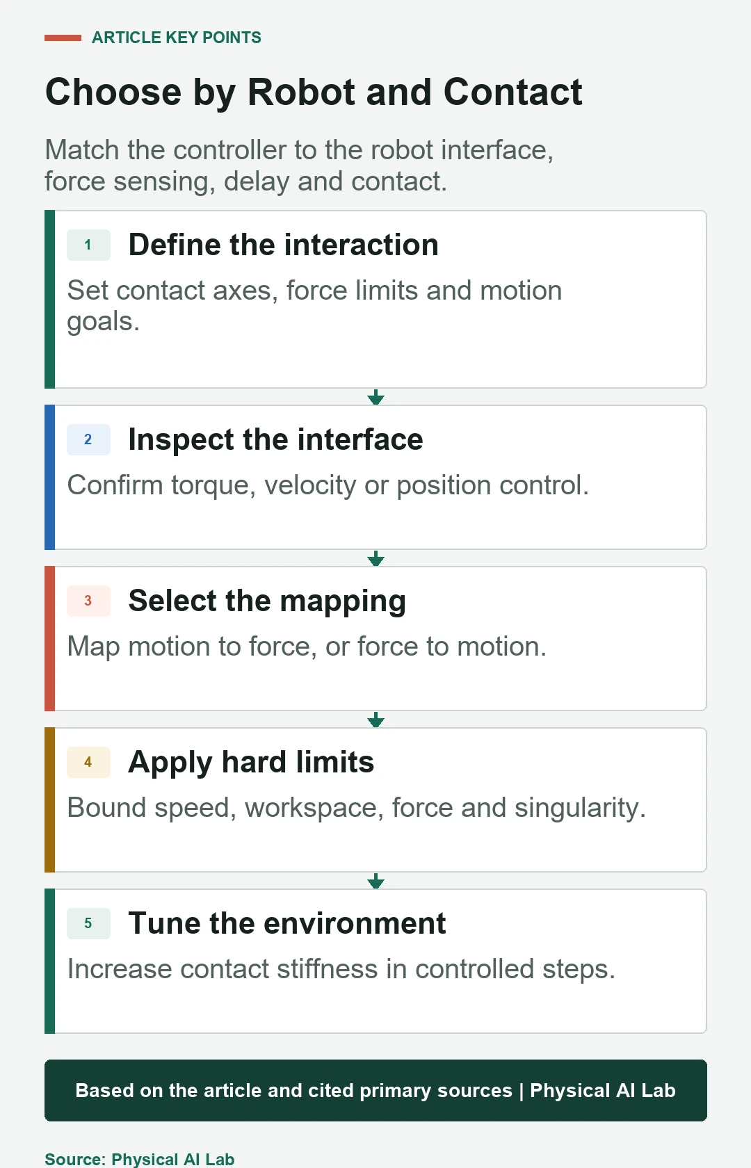
- Define controlled axes, frames and contact objectives.
- Match the mapping to the real command interface.
- Measure sensor and command latency.
- Apply workspace, speed, torque and force limits first.
- Tune from soft contact toward the real environment.
Frequently asked questions
Is impedance control the same as force control?
No. Impedance shapes a force-motion relationship; it may produce force behavior without commanding one constant force.
Can a position-controlled robot use impedance control?
It can emulate compliant behavior through admittance or outer-loop motion correction, but the hidden position servo limits the result.
Does lower virtual stiffness always mean safer motion?
No. Inertia, speed, delay, workspace limits, singularity and failure behavior still determine risk.
Will heavier force filtering always improve stability?
No. It reduces noise but adds delay and phase lag, which can worsen contact response.
Can one robot use both approaches?
Yes. Different layers or axes may use impedance-like and admittance-like mappings, provided their interaction is explicitly designed and tested.
Contact Control Boundary Note
Contact-control performance depends on robot mechanics, inner servo behavior, sensing, frames, delay and environment stiffness. Apply independent limits and the required safety functions, then validate the complete system under representative contact and fault conditions.