I compared two base-pivot locations for the same 100 mm output arm and the same actuator pin lengths. The near mount mapped 100, 125, and 150 mm lengths to arm angles of 41.41°, 55.77°, and 70.53°. Moving the base pivot 50 mm upward changed those angles to 56.20°, 70.65°, and 85.15°. Each layout reached the authored 65–75° requirement at one sampled length, but neither qualifying pose cleared the fixed frame: its rectangular barrel still had positive-volume intersection.
This was an AI-operated Blender 5.2.2 LTS concept experiment with six independently authored static cells. It tested pin-centre geometry and finite envelopes. It did not move a physical actuator or evaluate load, force, speed, control, or safety.
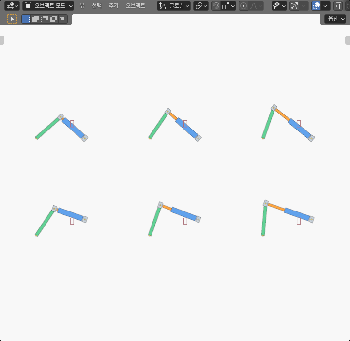
The same length produced different arm angles
The hinge was fixed at [0, 0] mm. The moving pin sat 100 mm from that hinge on the output arm. For the near layout, the actuator base pin was [150, 0] mm; for the offset layout it was [150, 50] mm. I used pin-centre lengths of 100, 125, and 150 mm. Their 50 mm span was an authored comparison range, not a product stroke specification. I entered metre equivalents in Blender. Display-cell offsets were 350 mm between columns and 300 mm between rows; I removed those offsets before comparing mechanism coordinates.
For each cell, the hinge-to-moving-pin distance remained 100 mm and the base-to-moving-pin distance matched the selected actuator length. I kept the positive-cross circle-intersection branch so the six poses belonged to one declared assembly family. Changing the base pivot changed the triangle, so actuator length alone could not determine arm angle.
| Mount and pin length | Measured arm angle | In 65–75° window? | Barrel versus frame |
|---|---|---|---|
| Near · 100 mm | 41.41° | No | Intersects · 1750.9 mm³ |
| Near · 125 mm | 55.77° | No | Intersects · 1750.9 mm³ |
| Near · 150 mm | 70.53° | Yes | Intersects · 1217.7 mm³ |
| Offset · 100 mm | 56.20° | No | Intersects · 33.0 mm³ |
| Offset · 125 mm | 70.65° | Yes | Intersects · 1.584 mm³ |
| Offset · 150 mm | 85.15° | No | Intersects · 33.0 mm³ |
Angle acceptance and frame clearance were separate gates
If I had checked only the requested angle window, both layouts would have appeared usable: the near mount qualified at 150 mm, and the offset mount qualified at 125 mm. The finite-body check rejected both sampled poses because their barrels intersected the frame.
The offset 125 mm case was especially instructive. Its intersection volume was only 1.584 mm³, but the independently reconstructed interior witness lay 85.42 micrometres inside the nearest finite XY boundary. That exceeded the 8 micrometre comparison allowance. It was therefore a supported positive-volume intersection, not a rounding artifact. The number is common solid volume, not penetration depth, deformation, damage, or contact force.
All six barrel poses intersected the frame. The rod and the two clevis envelopes remained disjoint from it in every sampled cell. That distinction matters when changing the design: moving the base or reshaping the barrel could address the observed conflict without implying that every actuator component needs the same change.
Finite envelopes prevented a centreline-only answer
The model used generic rectangular solids rather than product CAD: a 100 mm arm, barrel, rod, base-clevis envelope, moving-clevis envelope, fixed frame, and three reference markers. The markers were closed boxes used to recover centres. They were not drilled holes, bearings, or physical pins.
In the mechanism frame, the fixed obstacle occupied x = 105–115 mm, y = 35–55 mm, and z = −12–12 mm. The rectangular barrel extended from 8 to 88 mm along the base-to-moving-pin axis and was 16 mm wide and 16 mm thick. These authored envelopes made frame interference a separate constraint on the pivot layout.
The independent check reconstructed 54 closed prisms and all 432 evaluated vertices. It recovered pin centres, arm radius, pin length, arm angle, branch sign, and the four actuator-envelope-to-frame relations. The barrel intersections came from finite polygon and height overlap, while disjoint parts required genuine face or edge distance witnesses. This avoided treating object origins, centrelines, or a bounding box around a rotated part as the mechanism result. The numerical checks allowed 4 µm per coordinate and 8 µm when comparing two solids. Those allowances describe readback consistency; they are not manufacturing tolerances or evidence of hardware accuracy.
Internal overlap between the schematic barrel, rod, and clevis shapes was not an attachment or fit validation. The experiment also did not test bearing alignment, pin strength, side load, buckling, friction, or backlash.
Pivot terminology does not supply the layout
Firgelli’s mounting-bracket overview, checked on October 8, 2026, describes clevis-style mounting that lets actuator ends pivot as a driven member changes orientation. I used that manufacturer description only for mounting terminology. The base coordinates, arm radius, frame, rectangular envelopes, length samples, and required-angle window in this experiment were independently authored; no catalog dimensions or performance ratings were transferred.
This question also differs from our slider-crank and Scotch-yoke experiment, which compares dwell across a crank cycle. Here there was no timing or continuous cycle. It also differs from the tool-side slide-direction experiment, which projects linear travel onto a contact normal. Here the actuator length closed a triangle and set an arm angle.
Choose a mount only after both checks pass
A practical layout sequence is straightforward. First define the required arm-angle window. Then freeze the hinge, moving-pin radius, candidate base pivots, and actuator pin-length range in one frame. Solve the intended assembly branch, construct the full barrel, rod, clevis, arm, and frame solids, and evaluate angle membership and component clearance independently at each required pose.
For this authored frame, neither candidate earned selection: one sampled pose per layout reached the angle window, but both barrels intersected the frame. The next design iteration should change a real input—base location, frame shape, barrel envelope, arm pin radius, or required window—and repeat the finite checks.
The six cells do not certify an unsampled continuous angular range or a collision-free stroke between samples. They also say nothing about hardware loads, actuator capacity, control, speed, life, accuracy, installation, or safety. The useful conclusion is narrower: stroke range is an input to mechanism geometry, not a substitute for output-angle and full-envelope verification.