A robot encoder converts mechanical position into a digital or electrical measurement used for commutation, position, velocity, control and diagnostics. The right device depends on what shaft is observed, whether position must survive power loss, the required installed accuracy, update timing and environmental constraints.
Resolution is only the number of distinguishable counts or reported bits. Accuracy includes systematic error, eccentricity, interpolation, alignment and temperature. Repeatability, latency, noise and fault coverage can matter more than nominal resolution for a fast robot joint.
This guide connects feedback selection to robot actuator structure, transmission behavior and frameless motor commutation. Use current interface and safety documentation for the selected device.
An encoder can serve several control functions
The Renishaw encoder overview distinguishes sensing elements, scales and readheads used to measure position. In a robot, feedback can provide rotor angle for commutation, joint position, derived velocity, homing, calibration and monitoring.
List these functions before choosing a device. A motor commutation encoder may need high update rate and low jitter, while a calibrated arm output encoder may prioritize absolute position and installed accuracy. One signal can support both only if all requirements are satisfied.
Absolute and incremental encoders handle startup differently
An absolute encoder reports a unique position within one turn or across multiple turns, allowing the controller to know position after power-up without moving to a reference. An incremental encoder reports changes through pulses or digital counts and normally requires an index or homing reference.
Absolute feedback simplifies restart but adds interface, initialization, data-valid and possible battery or turn-count considerations. Incremental feedback can be fast and simple. The system should define behavior when stored multi-turn state disagrees with mechanical reality.
| Encoder choice | Main benefit | Main limitation | Robot use |
|---|---|---|---|
| Absolute single-turn | Position after power-up | No unpowered turn count | Joint angle within one revolution |
| Absolute multi-turn | Extended position history | State mechanism and reset rules | Linear or multi-turn axes |
| Incremental | Simple high-rate change measurement | Needs reference | Motor and velocity feedback |
| Dual encoder | Observes two sides of transmission | Cost and signal comparison | Precision or torque-aware joints |
Optical and magnetic encoders trade environment and accuracy
Optical encoders read patterned scales with light and can support fine interpolation and strong accuracy. They require control of contamination, alignment and optical geometry. Magnetic encoders sense a magnet or magnetic scale and can tolerate some dirt and compact packaging.
Magnetic devices can be affected by magnet placement, external fields, temperature and nonlinearity. Capacitive and inductive methods offer other tradeoffs. Technology labels do not replace an installed error budget under the robot’s actual environment.

Resolution, accuracy and repeatability must not be confused
A device can report many bits while retaining larger periodic or mounting error. Accuracy is the difference between reported and true position over the range. Repeatability describes how consistently a position is reported under repeated conditions. Precision language should name the actual quantity.
Create an error map using a traceable external reference. Sweep both directions and multiple speeds and temperatures. Store correction tables only when their validity and hardware identity are controlled; compensation cannot repair mechanical looseness or changing eccentricity.
Motor-side feedback supports commutation and fast control
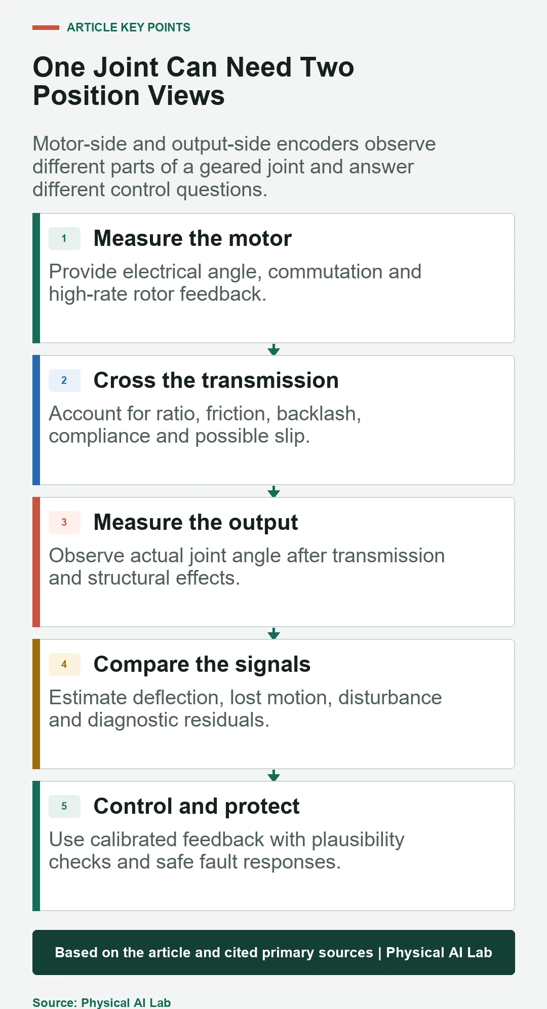
A motor encoder directly observes the rotor. It is useful for electrical-angle commutation, current and velocity loops, and high-rate motion control. In a geared joint it does not directly observe backlash, elastic deflection or slip after the motor shaft.
Encoder alignment to the rotor electrical field must be calibrated for brushless control. Invalid phase order or offset can reduce torque and increase current. Diagnostics should detect implausible angle steps, communication loss and disagreement with current or motion.
Output-side feedback observes the actual joint angle
An output encoder measures position after the reducer or transmission. It can improve joint accuracy and expose some lost motion or compliance. Its bandwidth, mounting and structural reference should match the controller’s needs.
Combining motor and output signals creates a dual-encoder architecture. Their difference includes transmission ratio, elastic deflection, backlash and measurement errors. Filters and observers must respect delay and noise to avoid unstable control.
Interfaces and timing affect closed-loop performance
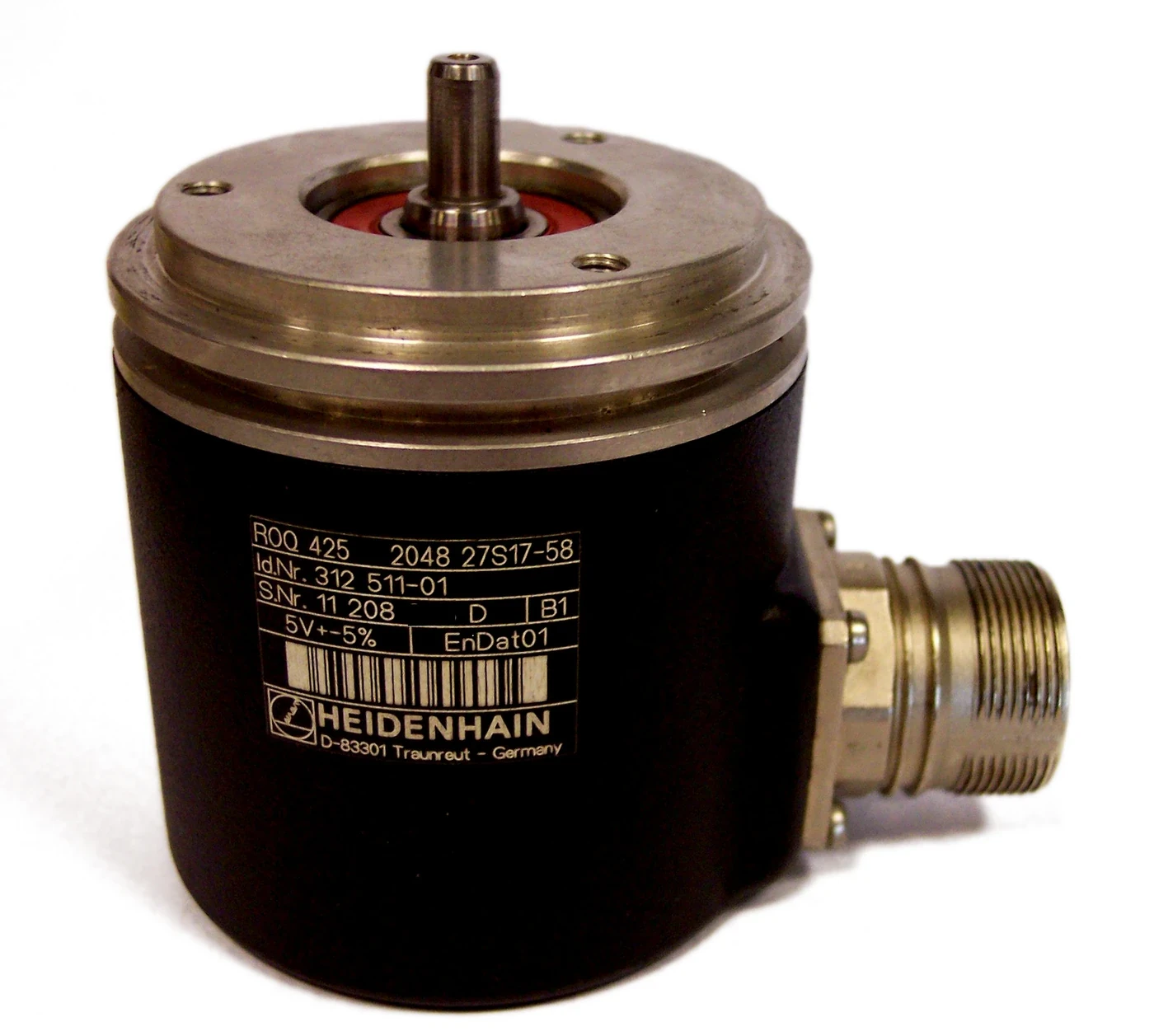
Analog sine-cosine, quadrature, SPI, BiSS, EnDat and other interfaces differ in wiring, initialization, bandwidth, diagnostics and implementation. A high nominal update rate is not useful if bus scheduling, conversion and software add variable latency.
HEIDENHAIN publishes robotics feedback examples that illustrate compact motor and joint measurement. For any interface, record sample time, transfer delay, timestamp quality, jitter and fault response inside the actual drive.
| Error source | Effect | Detection | Mitigation |
|---|---|---|---|
| Eccentric mounting | Periodic angle error | Reference sweep | Mechanical alignment or map |
| Temperature | Scale or electronics drift | Thermal calibration | Compensation and limits |
| Communication delay | Phase lag | Timestamp measurement | Interface and scheduling design |
| Electrical noise | Jumps or corrupted frames | CRC and plausibility | Shielding and fault handling |
| Transmission deflection | Motor/output disagreement | Dual feedback under load | Model and output sensing |
Environment and mechanics shape installed accuracy
Vibration, impact, dust, moisture, oil, temperature and magnetic fields can affect feedback. Shaft runout, bearing play, readhead gap and scale attachment may change during loading. Cable routing must survive repeated robot motion without injecting noise or intermittent faults.
Review ingress and shock ratings with the complete enclosure. Test after assembly and after environmental exposure. A clean-room measurement cannot establish performance in a warm, moving joint with power electronics nearby.
Safety functions need diagnostics beyond position data
A standard encoder may provide accurate control feedback without the redundancy or diagnostic coverage required for a safety function. Safe position or speed architectures can use diverse channels, monitored interfaces and plausibility checks defined by the system safety design.
Do not infer a safety rating from resolution or an absolute interface. Evaluate dangerous failure modes, common causes, power and communication faults, software assumptions and the required safe state. Follow the current device certificate and integration manual where applicable.
Validation should close the full feedback loop
Use a traceable external reference to measure absolute error, repeatability, velocity noise, latency and startup behavior. Repeat across direction, load, speed, bus activity and temperature. Inject disconnection, corrupted data, frozen value and implausible jump faults.
Compare multiple units and aged joints. Confirm that calibration travels with the correct hardware and can be restored after service. A suitable encoder system is one whose installed feedback supports stable control, diagnostics and safe recovery with measurable margin.
- Define every feedback function.
- Separate resolution from installed accuracy.
- Choose motor, output or dual placement.
- Measure latency, jitter and environmental error.
- Validate startup, calibration and fault responses.
Frequently asked questions
What is the difference between absolute and incremental encoders?
Absolute encoders report a position after power-up, while incremental encoders report movement and normally require a reference or homing process.
Is a higher encoder resolution always better?
No. Resolution does not guarantee accuracy, repeatability, low noise or low latency. The full installed error budget must meet the control need.
Why use two encoders in a robot joint?
Motor-side feedback supports commutation and fast control, while output-side feedback observes position after the transmission and can reveal deflection or lost motion.
Are magnetic encoders less accurate than optical encoders?
Not universally. Each technology has product-specific accuracy and environmental behavior. Compare calibrated installed performance for the application.
Can any encoder be used for robot safety?
No. Safety functions require an architecture, diagnostics and certified integration evidence appropriate to the required risk reduction, not merely a position signal.
Position Feedback Note
Encoder performance depends on mounting, interface, timing, temperature and calibration. Verify the current device documentation and any safety certificate, then measure the installed joint with a traceable reference.