Choose a transport height with the carried object included in the geometry check. In this Blender comparison, a cube-bottom height of 40 mm produced no detected gripper penetration, yet the cube penetrated the receiving bin in 37 sampled poses. Raising its bottom to 60 mm removed detected penetration and unintended contact candidates from the sampled route. That makes 60 mm a condition worth examining further, not a measured minimum height for a real robot.
Codex ran this virtual comparison in Blender 5.2.2 LTS on October 5, 2026. A 60 mm cube moved with a prescribed gripper pose; the scene did not calculate whether the fingers could hold it. The downloadable transport-height experiment files (ZIP) contain a starting scene export, the unchanged script, and records separating gripper penetrations from payload penetrations across five conditions.
Throughout this article, transport height means the cube’s bottom above the worktable during horizontal travel. It is not the cube-center height or a robot tool-center-point setting. For this 60 mm cube, the 40 mm condition puts its center 70 mm above the table. The bin wall rises to 54 mm.
The preceding layout study separated camera visibility from approach space. The added question here is which part of the carried assembly reaches the bin rim.
Follow the cube past the rim at 40 mm
The cube first rose vertically, then followed a straight horizontal line into the left bin, and finally lowered to its floor. The horizontal route ran from X = 0, Y = 0 to X = −245, Y = 100 mm. At placement, the cube bottom was 8 mm above the worktable, matching the bin-floor top. The bin’s inner dimensions were 150 × 130 mm.
The modeled pad opening stayed at 60 mm, and the cube’s position relative to the gripper stayed fixed. Those assumptions let the comparison isolate height without introducing a new grasp or a different route.
The 40 mm raw record shows the problem clearly: the gripper had zero penetration samples while the cube had 37. The orange cube extends below the fingers, so checking the fingers alone misses the part of the moving assembly that meets the rim.
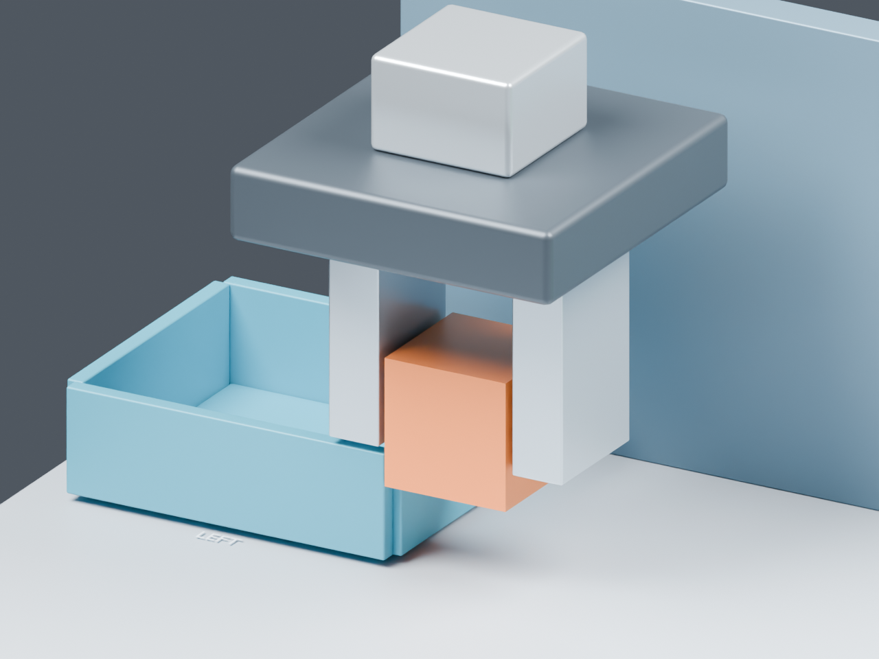
The next image keeps the same horizontal position and diagnostic camera while raising the cube bottom to 60 mm. Its nominal height above the 54 mm rim is now 6 mm. This subtraction describes the cube-to-rim height difference; it is not a general clearance measurement for the whole robot.
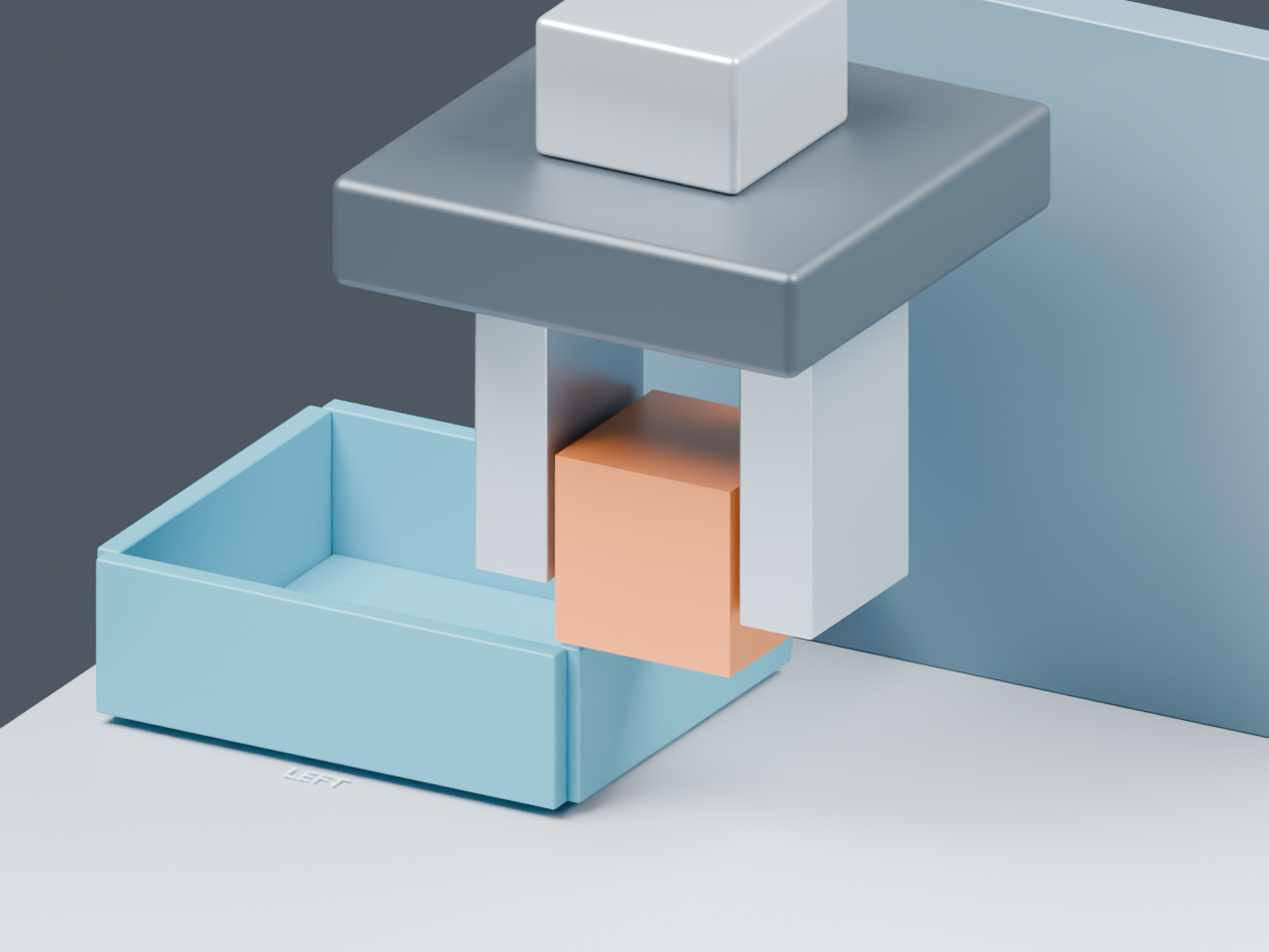
Both frames are comparison poses, not first-contact records or completed transfers. The 40 mm run first recorded penetration at a horizontal-route fraction of 0.541353; the images were deliberately rendered at 0.55. The scene and camera verification records the shared diagnostic camera. The higher frame crops the top mount, so it cannot establish whole-arm clearance.
What changes at the wall’s 54 mm height
Matching the wall height removed detected penetration but left a contact boundary. At a 54 mm cube-bottom height, 36 sampled poses contained unintended contact candidates. The cube had no nominal vertical allowance above the rim.
Here are the results across the complete prescribed paths. Each penetration column counts poses containing at least one qualifying component–obstacle overlap, rather than individual collision pairs.
| Cube-bottom height during transfer | Poses checked | Gripper penetration | Payload penetration | Either penetrated |
|---|---|---|---|---|
| 20 mm | 150 | 49 | 37 | 67 |
| 40 mm | 170 | 0 | 37 | 37 |
| 54 mm | 184 | 0 | 0 | 0 |
| 60 mm | 190 | 0 | 0 | 0 |
| 100 mm | 230 | 0 | 0 | 0 |
Gripper and payload counts overlap. At 20 mm, adding 49 and 37 would count some poses twice; the recorded total is 67. The geometry calculation also continued after the first penetration. These totals describe a prescribed path inspected in software, not a robot completing an obstructed movement.
At 60 and 100 mm, the sampled paths contained neither penetration nor unintended contact candidates. The taller path still needs interpretation. A 100 mm cube-bottom height gives a nominal 46 mm difference above the rim, but 46 mm is not the minimum gap along the route. In the 100 mm raw record, the smallest signed projection gap during horizontal travel was 11.605968 mm, between the gripper palm and the divider at the destination. Another part of the assembly became the limiting pair. That projection value is not a general shortest surface distance.
The experiment script sampled translations no more than 2 mm apart. It tested the evaluated component meshes against the surrounding geometry. A projection overlap beyond 0.001 mm had to produce a computed intersection volume greater than 0.000001 mm³ in Blender’s Exact Boolean solver to be classified as penetration. Near-zero projection gaps were contact candidates. These thresholds describe numerical classification; they do not specify manufacturing tolerances. Intentional cube contact with the table or bin floor was allowed, while penetration remained reportable.
The bundled JSON records preserve all five height conditions; the supplied Blender file is the starting layout, not the five generated experiment scenes. None of the recorded conditions establishes continuous clearance between samples, grip retention, robot reachability, or tracking accuracy. The run also measured no time, energy, or load penalty for lifting higher, and it did not compare a route around the bin.
For your next scene check, mark the payload’s lowest surface and express its transfer height from the same reference as the obstacle top. Include the carried geometry alongside the gripper, keep the horizontal route fixed while comparing heights, and inspect which component–obstacle pair limits each result. Carry the selected geometry into separate checks of the actual grasp and robot motion before treating a clear sampled path as an executable transfer.