A correct gear ratio does not guarantee that two spur gears will mesh through every angle. For the ideal 20/40-tooth pair examined here, 60 mm is the nominal center distance, and 61 mm still permits continuous active-involute contact. Moving the shafts to 59.5 mm makes the unthinned teeth overlap; moving them to 62 mm leaves intervals with no active tooth pair in contact. A scripted 2:1 animation can keep rotating through both failures.
The useful check is therefore threefold: establish the reference geometry, calculate how the operating contact path changes with shaft spacing, and check whether the teeth themselves fit that spacing.
What the 60 mm dimension actually means
Use matching module, reference pressure angle and tooth form before comparing center distances. This example fixes module m = 2 mm, tooth counts z₁ = 20 and z₂ = 40, and reference pressure angle α = 20°. Both profile shifts are zero. Each ideal tooth occupies half the circular pitch at its reference circle, with no deliberate thinning.
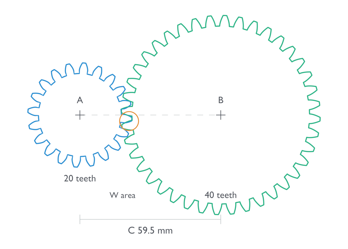
The overview below shows the same ideal tooth pair at 59.5 mm shaft spacing and 0° input. A and B locate the shaft centers; the orange ring identifies the W interface shown at larger scale later. Blue denotes the pinion and green the wheel throughout the figures. These measured-boundary schematics do not measure physical penetration depth.
The reference radii and nominal shaft spacing are
rᵢ = mzᵢ/2; a₀ = r₁ + r₂ = m(z₁ + z₂)/2 = 60 mm.
The pinion and wheel therefore have reference radii of 20 and 40 mm. Their addendum radii are 22 and 42 mm. These dimensions follow the standard, non-profile-shifted spur-gear construction in KHK’s gear-dimension reference.
The tooth-count ratio makes the wheel turn at half the pinion’s speed in the opposite direction during conjugate engagement. That ratio does not specify tooth thickness, tip height, or the available contact path. Giving two objects that rotation rule cannot supply missing contact.
Involute teeth can accommodate some extra spacing
An involute is generated by unwinding a taut string from a base circle. For the fixed tooth profiles here, the base radii stay unchanged:
rᵦ,ᵢ = rᵢ cos α.
The common tangent to the two base circles defines the line of action. At a changed center distance a, its operating pressure angle is
αw = arccos[(rᵦ,₁ + rᵦ,₂)/a].
At 61 mm, this angle becomes approximately 22.44°. The reference tooth form is still the same 20-degree involute. This distinction matters: increasing the shaft spacing changes the operating geometry, rather than automatically invalidating the involute speed ratio. KHK describes this center-distance accommodation in its involute tooth-form explanation.
Accommodation has a limit. As the shafts move farther apart, the addendum circles intercept a shorter usable portion of the line of action. Eventually, one tooth pair leaves that portion before the next arrives.
Calculate whether the next pair arrives in time
Let rₐ,ᵢ denote each addendum radius. For this external pair, the active contact-path length is
ℓ = √(rₐ,₁² − rᵦ,₁²) + √(rₐ,₂² − rᵦ,₂²) − a sin αw.
The transverse contact ratio is
ε = ℓ/pᵦ; pᵦ = πm cos α.
Use the reference pressure angle in the base pitch; it remains approximately 5.9043 mm for these unchanged profiles. KHK defines the contact path from the addendum-circle intersections and relates its length to base pitch in its path-of-contact reference.
A contact ratio above one gives overlapping engagement intervals for successive pairs. Below one, the ideal active flanks have periodic contact gaps. Equality leaves no overlap reserve. This calculation also assumes that the path stays above both base circles; that condition holds for all four spacings considered here.
The following values come from the analytical model of the same fixed teeth. The native Blender sweep independently checked matching flank vertices, contact counts and overlap witnesses for these four spacings:
| Center distance (mm) | Operating angle | Contact ratio | Signed tooth-space balance (mm) | Geometric result |
|---|---|---|---|---|
| 59.5 | 18.63° | 1.891 | −0.349 | Active tooth material overlaps |
| 60 | 20.00° | 1.635 | 0.000 | Continuous ideal active contact |
| 61 | 22.44° | 1.167 | +0.784 | Continuous contact, more tooth-space clearance |
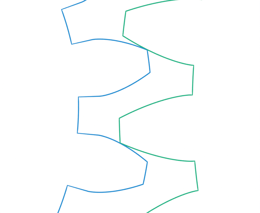
| 62 | 24.58° | 0.743 | +1.675 | Periodic active-contact gaps |
For this particular pair, solving ε = 1 places the geometric upper boundary near 61.384 mm. It is a useful design warning, not a recommended assembly tolerance. Changing the tooth addenda or profiles changes that boundary.
At 62 mm, the continuous model leaves approximately 25.7% of each repeating engagement interval uncovered. A half-degree sweep with the specified contact phase finds no active pair at 180 of 720 unique input angles. The sampled 25% differs from the continuous fraction because the grid samples interval boundaries discretely. These are angle fractions; interpreting them as time fractions requires constant input speed.
Closer shafts can produce a different failure
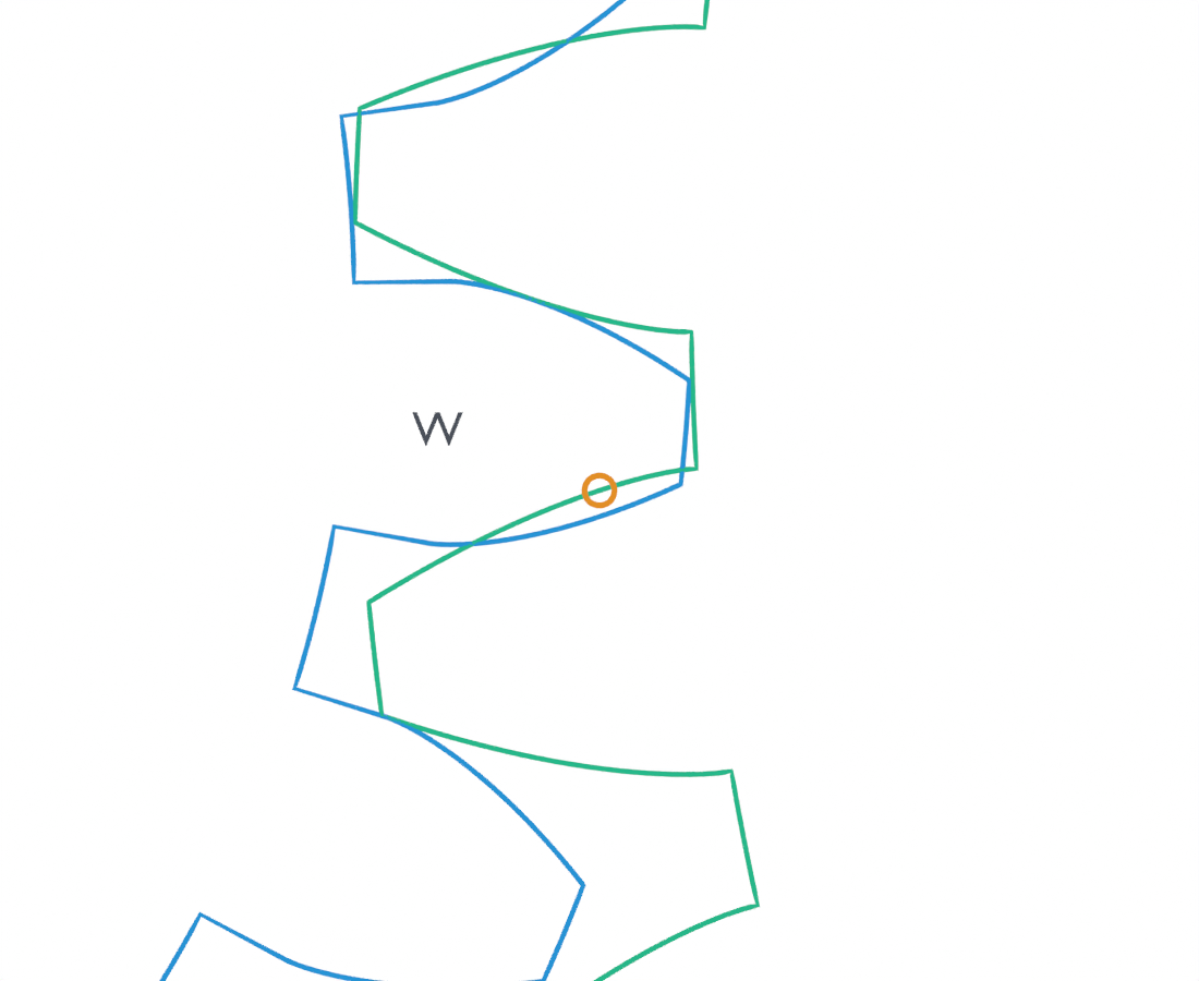
The 59.5 mm case has a larger formal contact ratio than the nominal pair. That does not rescue it: the unchanged teeth are too thick for the reduced working tooth spaces.
For these ideal, unthinned teeth, define
j = 2a[inv(αw) − inv(α)]; inv(x) = tan x − x.
with angles in radians. Positive j is the theoretical circumferential backlash at the working pitch circles. A negative value is a signed tooth-space deficit, not a physically available negative gap or a measured backlash. At 59.5 mm, the deficit is approximately 0.349 mm.
A separate geometric test supports this conclusion: transform an active flank point into the other gear’s coordinates, then check whether it lies strictly inside that gear’s ideal tooth material between its base and addendum circles. The actual world-coordinate sweep found such an overlap witness at all 720 unique sampled input angles for 59.5 mm. This identifies active-flank overlap; it should not be mislabeled cutter undercut or assumed to be a root-fillet collision.
Check the geometry before trusting the animation
Start with a₀, then calculate αw, the contact ratio and the signed tooth-space balance at the proposed spacing. Keep the angular phase consistent with one contact side when inspecting the teeth. A visually plausible frame or a correct rotation ratio cannot replace these checks.
If the gear output drives a linkage, check that linkage’s available input travel separately. Our four-bar crank-rotation study examines when assembly geometry admits every input angle; a working gear mesh alone does not answer that question.
Codex executed the study through Blender MCP on October 5, 2026 in Blender 5.2.2 LTS. It recorded 2,884 poses: 721 per spacing from 0° through 360° in 0.5° steps. Counts exclude the duplicate 360° endpoint. Contact candidates were calculated along the line of action, then checked against matching actual flank mesh vertices transformed into world coordinates. A separate verifier reconstructed those points with a Cartesian unwound-string involute, without importing the experiment’s geometry helper. All contact-count and overlap-witness checks passed the 0.0001 mm coordinate and 0.000001 rad prescribed-phase audit thresholds; these are software checks, not manufacturing tolerances.
This is prescribed planar geometry, with illustrative radial joins below the base circles. Absence of an active-flank overlap witness does not certify the complete tooth root or tip-to-root clearance. Manufactured profiles, deliberate backlash, tolerances and load requirements need their own checks; this model does not establish contact forces or hardware performance.