Two neighboring thread traces can be 2 mm apart while one revolution corresponds to 6 mm of axial advance. That happens in the three-start geometry here: three separate helices share the visible spacing. Entering 2 mm as the distance per revolution would make the ideal turn-to-travel scale wrong by a factor of three.
The distinction is between pitch, the axial spacing of adjacent thread traces, and lead, the axial advance along one start over a full turn. Haydon Kerk Pittman’s Lead Screws 101 defines lead as travel per screw rotation and uses a helix as a conceptual simplification of the thread. The examples below examine that geometry; their dimensions are synthetic, not specifications of a selected product.
Follow one path through the apparent repetition
Consider three ideal helical centerlines around a 4 mm radius, each extending from axial position 0 to 24 mm. Their starting angles are 0°, 120° and 240°. With a 2 mm pitch, each individual helix advances 6 mm in one complete turn: lead equals pitch multiplied by the number of equally spaced starts.
Look at their intersections with one fixed angular direction. There are crossings at axial positions 0, 2, 4 and 6 mm. The first and fourth belong to the same blue start; the two in between belong to the other starts. Measuring from 0 to 2 mm changes paths. Following the original path until it returns to that angular direction reaches 6 mm instead.
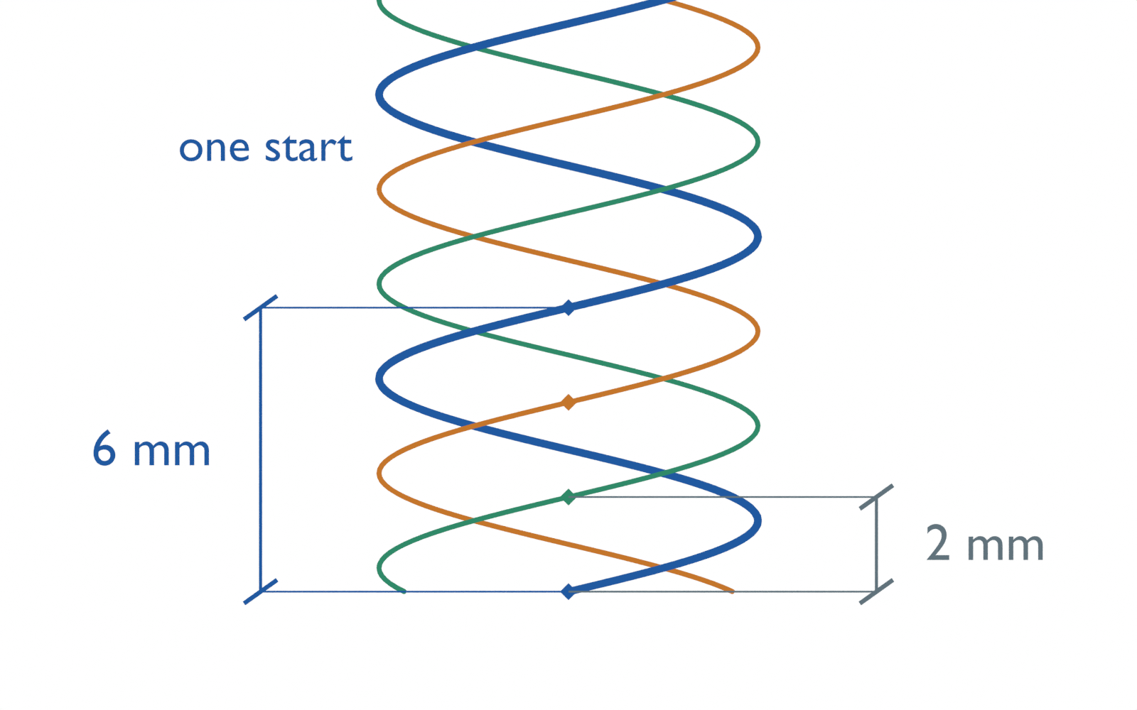
That is why a side view of repeated ridges can hide the relevant distinction. In the single-start comparison, also with a 2 mm pitch, the successive 0, 2, 4 and 6 mm crossings all lie on one helix. There, a full turn advances 2 mm and pitch equals lead.
In an AI-operated Blender 5.2.2 LTS study on October 5, 2026, we kept every start as its own open connected mesh path. Across 102 evaluated poses, an independent audit measured the gaps between neighboring fixed-direction crossings and unwrapped the angle along each individual path to obtain its one-turn advance. It confirmed 2 mm spacing in both examples, with 2 mm lead for one start and 6 mm lead for three starts. The displayed paths are copied from the actual evaluated three-start mesh, preserving their separate identities.
The checks also rejected a broken path and an attempt to measure one-turn advance between two different starts. Those are geometry and implementation checks. No manufactured thread, nut contact, load, backlash, deformation, efficiency or positioning accuracy was tested.
Use lead in the turn-to-travel conversion
Suppose the desired displacement is 4 mm and the three-start geometry has a 6 mm lead. The ideal conversion asks for 2/3 of a revolution. Using its 2 mm pitch as the distance per revolution instead asks for 2 revolutions. Those two revolutions correspond to 12 mm of displacement in this geometry.
The 12 mm result is a calculated scale error, not a hardware calibration measurement. The model prescribes rotation of an axially fixed helix and follows a nonrotating phase-reference point on one start. It has no mating nut or mechanical contact solver. The manufacturer’s conceptual helix explanation supports the definition of lead; it does not validate our scene or supply these dimensions.
For the direction convention used here, positive drive means clockwise when viewed from the positive end of the axis. The right-handed geometric helix stays axially fixed, while the reference point moves toward increasing axial position. This explicit convention prevents a reversed sign from masquerading as a pitch-versus-lead error; it does not determine a machine’s positive-axis setting.
The following executed Python reproduces the distances and scale error. All distances are millimeters. entered_mm_per_rev is an assumed conversion scale; no motor or controller setting was applied.
pitch_mm = 2.0
requested_mm = 4.0

for starts in (1, 3):
    lead_mm = pitch_mm * starts
    turns = requested_mm / lead_mm
    print(f"{starts} start(s): lead={lead_mm:.3f} mm/rev, turns={turns:.3f}")

actual_lead_mm = pitch_mm * 3
entered_mm_per_rev = pitch_mm
wrong_turns = requested_mm / entered_mm_per_rev
ideal_displacement_mm = wrong_turns * actual_lead_mm
print(f"Pitch entered as lead: {wrong_turns:.3f} turns -> {ideal_displacement_mm:.3f} mm")
The finite ends matter even in this simplified geometry. The tracked point starts at 6 mm; on the three-start trace it reaches 24 mm after three positive turns. At that endpoint a point still exists on the drawn helix, but no trace remains beyond it. Requests past the end return no corresponding point. The calculation neither jumps to another start nor treats an endpoint point as sufficient engagement for a real nut.
For the conversion, identify lead in distance per revolution and retain the start count that explains it. Counting neighboring ridges supplies pitch; following one continuous start supplies the missing one-turn distance. Contact architecture, load, speed, preload and structural limits remain separate choices, covered in the ball screw versus roller screw selection guide.